ES4440.2 Compact Failure Simulation Module - User’s Guide 33
ETAS Pin Assignment
3.4 ”Current” Connector
The current between the two failure rails can be measured at the ”Current” con-
nector. The direction of the current is unimportant which is why the two jacks are
not defined more precisely.
Type: Banana jacks
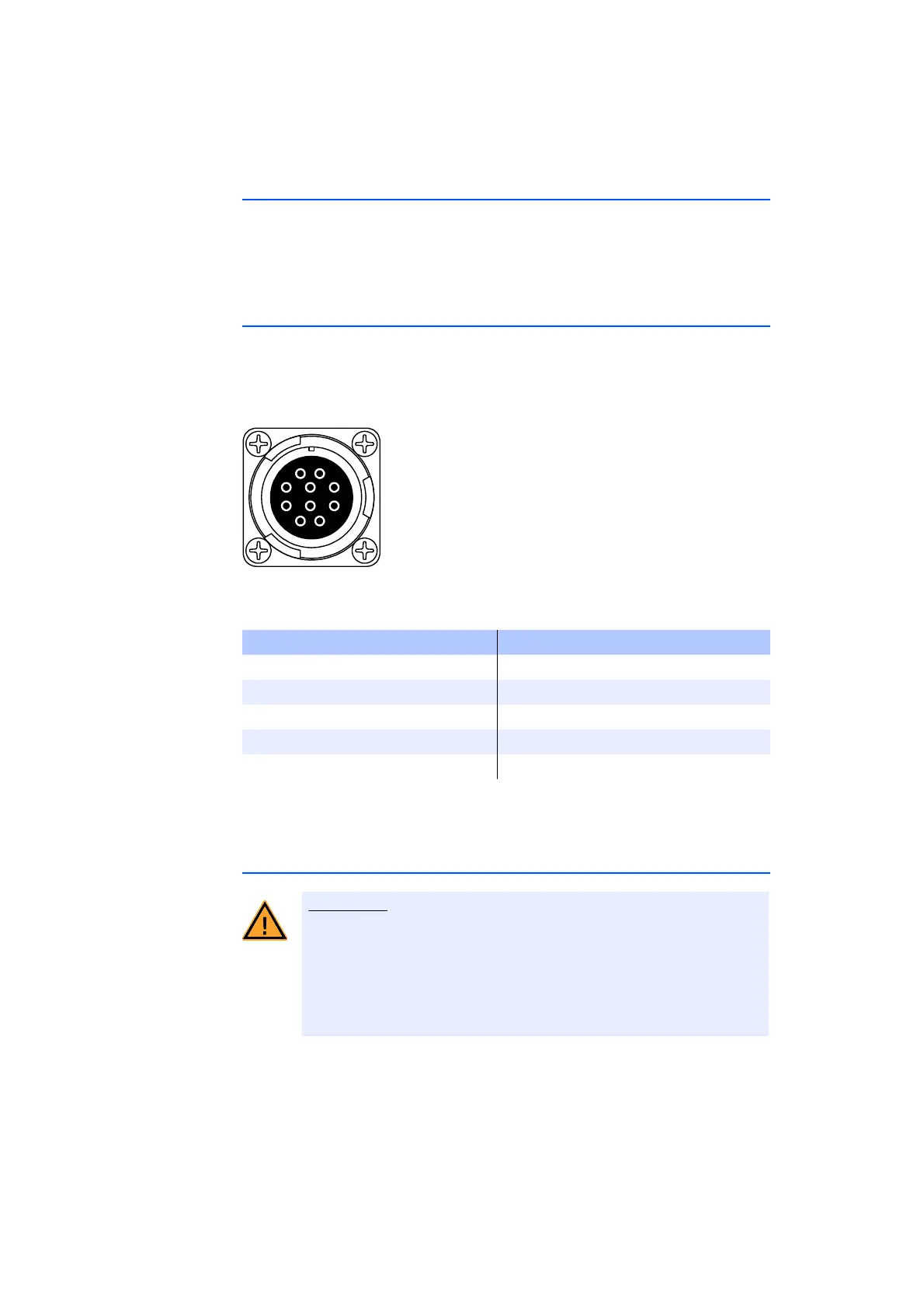
3.5 ”Rail 1/2” Connector
The ”Rail 1/2” connector is used to connect the two failure rails of a master to
those of the connected slave systems and to connect to +/- U_Batt (A/B/C).
Type: ITT Cannon CA02COM-E18-1S-B-01 (female)
Counterpart: ITT Cannon CA06COM-E18-1P-B-01 (male)
Fig. 3-4 ”Rail 1/2” Pin Assignments
Tab. 3-4 ”Rail 1/2” Pin Assignment
3.6 ”ECU HV” Connector
The 16 high-voltage channels of the ECU are connected via these two connec-
tors.
Type: ITT Cannon CA02COM-E20-29P-B (male)
Pin Assignment Pin Assignment
A Rail 1 F -UBatt_B
B Rail 2 G internal use
C +UBatt_A H +UBatt_C
D -UBatt_A I -UBatt_C
E+UBatt_B J n.c.
Risk of electric shock!
There could be extremely dangerous high voltages at the individual
pins of the "ECU HV" and "LOAD HV" connections. Therefore you
should only open the housing when the device has been discon-
nected from the mains power and all other connections have been
removed.