Operating Instructions
Non-Contact Safety Switch CES-AR-C01-…
16
(Translation of the original operating instructions) 2098039-20-02/20
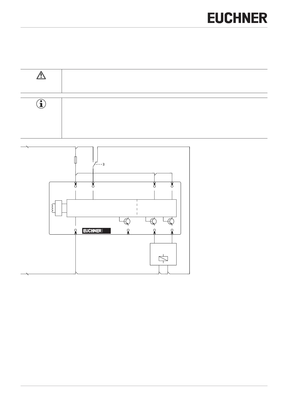
9.8. Connection of a single AR device
If a single AR device is used, connect the device as shown in Figure 3. Monitoring outputs can be routed to a control system.
The switch can be reset via the RST input. To do this, a voltage of 24 V is applied to the RST input for at least 3 seconds.
The RST input must be connected to 0 V if it is not used.
WARNING
In the event of a fault, loss of the safety function due to incorrect connection.
Ì To ensure safety, both safety outputs (OA and OB) must always be evaluated.
Important!
The example shows only an excerpt that is relevant for the connection of the CES system. The example
illustrated here does not show complete system planning. The user is responsible for safe integration
into the overall system. Detailed application examples can be found at www.euchner.com. Simply enter
the order number of your switch in the search box. You will nd all available connection examples for
the device in Downloads.
Safety
Outputs
Monitoring
Output
Read Head
-B1
UB
2
IA
6
IB
1
7
0V
5
OUT
3
OA
4
OB
RST
8
CES
Safety Inputs
GND
-F1
Connected
load
-S1
Figure 3: Connection example for separate operation of a CES-AR-…

 Loading...


