PROTEUS user manual
Issue C
24
PROTEUS COM Express
The PROTEUS V1I1 COM Express provides two single-channel 24-bit LVDS interfaces
to COM Express board to board connector. For more information how to use LVDS see
your COM express base board manual.
Using the backlight connector
The PROTEUS provides one +5V backlight connector (J20).
See J20 - Backlight
, page 57 for more information.
Using the touchscreen interface
The PROTEUS provides a touchscreen interface. A touchscreen controller is placed on
the PROTEUS board and uses Eurotech TSC1 firmware.
4-wire and 8-wire touchscreens are directly supported.
See J18 – Touchscreen
, page 55 for more information.
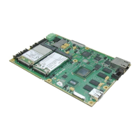
Using the PCIE minicard sockets
The PROTEUS provides two PCIE minicard sockets. PCIE minicard socket 0 also
provides SIM card interface (J12).
See J12 - SIM card socket
, page 52 for more information.
PROTEUS stand alone
PCIE minicard socket 0 (J13) is connected directly to the Intel System Hub Controller
US15W. Some cards may require direct PCIE connection to the controller and may not
work via a switch. PCIE minicard socket 1 (J14) is connected to on board PCIE switch.
See J13 - PCI Express Mini Card slot 0
, page 53 and J14 - PCI Express Mini Card slot 1,
page 54
for more information.
COM Express
Both PCIE minicard sockets (J13, J14) are connected to the PCIE switch.
Using the micro SD
The PROTEUS provides one micro SD slot (J24). The slot supports micro SD cards with
a capacity up to 2GB.