EVCO S.p.A.
c-pro 3 nano CHIL | Application manual ver. 1.0 | Code 144CP3NCHE104
page 47 of 90
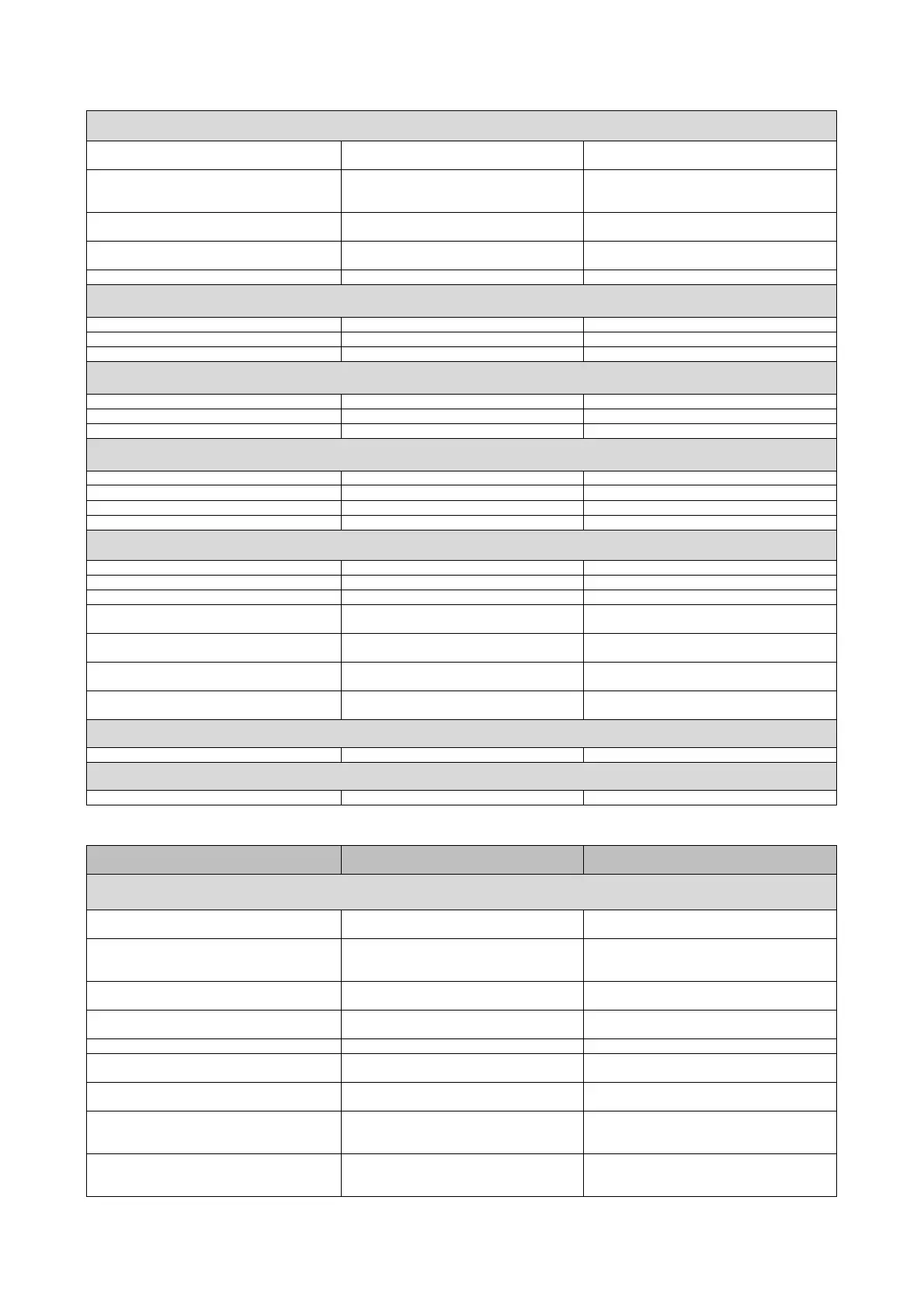
Digital Inputs Controller
D/I 1 On/Off (NC) On/Off
D/I 2 Heat sink exchanger flow switch (NC) Heat sink exchanger flow switch (NC)
D/I 3 Fan thermal switch C1 (NC) Fan thermal switch C1 (NC)
D/I 4 Compressor thermal switch 1 (NC) Thermal switch pump 1 plant (NC)
D/I 5 Summer/Winter (NC) Summer/Winter (NC)
Digital inputs EVDRIVE03 circuit 1
D/I 1 VCM1 High pressure C1 High pressure C1
D/I 2 VCM1 Low pressure C1 Low pressure C1
D/I 3 VCM1 Compressor 1 thermal switch Compressor1 thermal switch
Digital inputs EVDRIVE03 circuit 2
D/I 1 VCM2 None High pressure C2
D/I 2 VCM2 None Low pressure C2
D/I 3 VCM2 None Compressor 4 thermal switch
Analogue Outputs Controller
A/O 1 VentilationC1 (PWM) Ventilation C1 (PWM)
A/O 2 Not used Not used
A/O 3 Not used Not used
A/O 4 Not used Not used
Digital Outputs Controller
D/O 1 Pump 1 plant (NO) Pump 1 plant (NO)
D/O 2 Compressor 1 (NO) Compressor 1 (NO)
D/O 3 Compressor 2 (NO) Compressor 4 (NO)
D/O 4 Anti-freeze heater plant C1 (NO) Anti-freeze heater plant C1 (NO)
D/O 5 Ventilation C1 (Enable) (NO) Ventilation C1 (single - Enable) (NO)
D/O 6 Not used Reversing valve C2 (NO)
D/O 7 Reversing valve C1 (NO) Reversing valve C1 (NO)
Digital Outputs EVDRIVE03 circuit 1
D/O VCM 1 Solenoid valve C1 Solenoid valve C1
Digital Outputs EVDRIVE03 circuit 2
D/O VCM 2 None Solenoid valve C2
8.2.4 Water/water and air/water heat pump no EVDRIVE03
PGUT=4 and 8 (1 Circuit) PGUT=12 and 16 (2 Circuits)
Analogue inputs Controller
A/I 1 Heat sink exchanger input temperature Heat sink exchanger input temperature
A/I 2
Heat sink exchanger output temperature
Circuit 1
Heat sink exchanger output temperature
Circuit 1
A/I 3 External room temperature Not used
A/I 4 Compressor discharge temperature C1 Not used
A/I 5 Coil temperature C1 Coil temperature C1
A/I 6 Compressor thermal switch 1 (NC) Compressor thermal switch 1 (NC)
A/I 7 Summer/Winter (NC) Coil temperature C2
A/I 8 Evaporation pressure C1 (4-20mA) Single pressure C1 (4-20mA)
A/I 9 Condensation pressure C1 (4-20mA) Single pressure C2 (4-20mA)

 Loading...


