EVCO S.p.A.
c-pro 3 nano CHIL | Application manual ver. 1.0 | Code 144CP3NCHE104
page 39 of 90
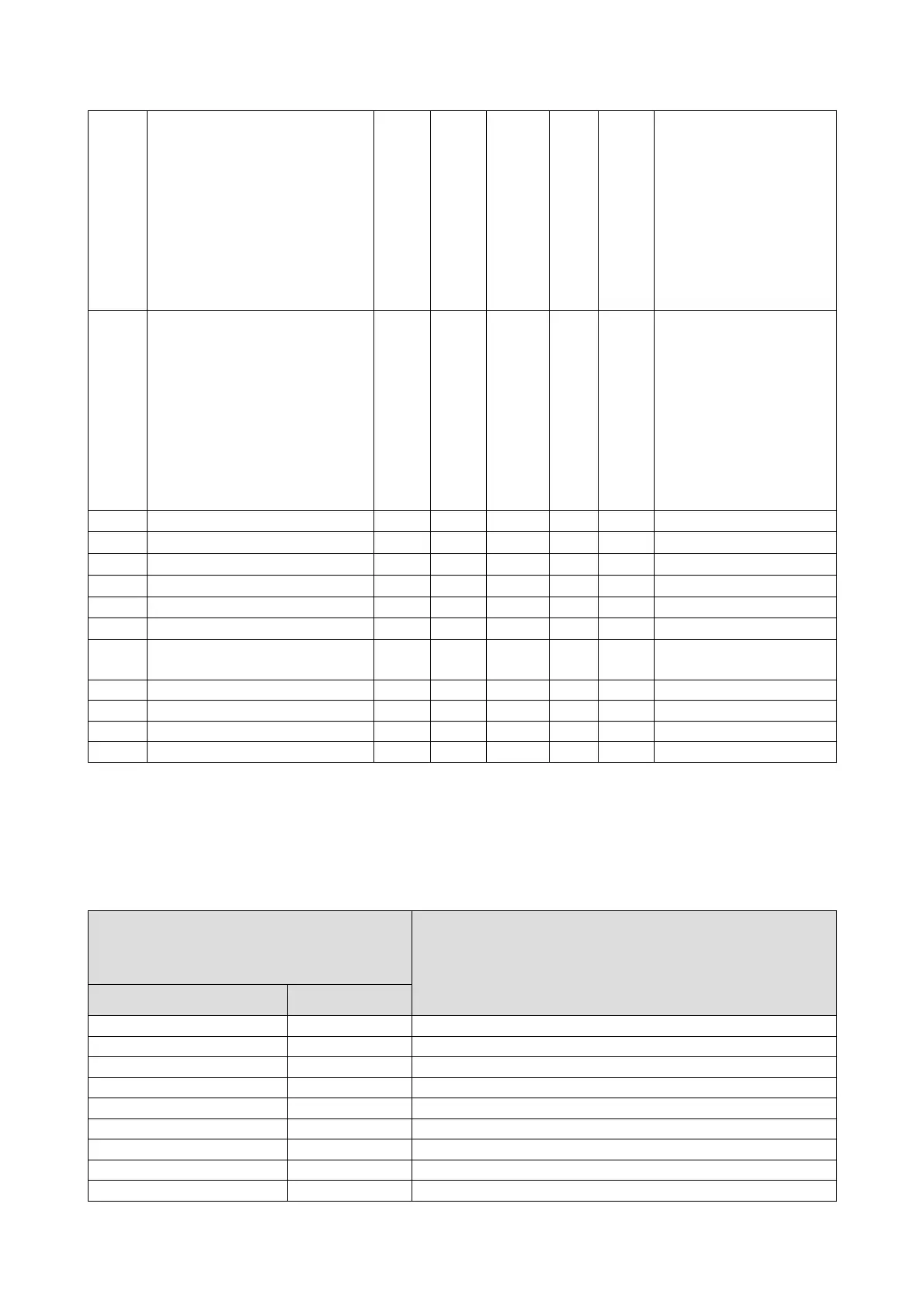
PV69
Probe type 1:
1= PTC
2= NTC
3= 0..20mA
4= 4..20mA
5= 0-5V
6= 0-10V
7= PT1000
8= NTC K2
9= NTC K3
5 1 9 CO-V
PV70
Probe type 2:
1= PTC
2= NTC
3= 0..20mA
4= 4..20mA
5= 0-5V
6= 0-10V
7= PT1000
8= NTC K2
9= NTC K3
2 1 9 CO-V
PV71 Offset Ts 0.0 -10.0 10.0 K CO-V
PV72 Offset Te 0.0 -10.0 10.0 K CO-V
PV74 Relay logic N.O. (0)
N.O. (0)
N.C. (1) CO-V
PV75 DI1 Logic N.O. (0)
N.O. (0)
N.C. (1) CO-V
PV76 DI2 Logic N.O. (0)
N.O. (0)
N.C. (1) CO-V
PV77 DI3 Logic N.O. (0)
N.O. (0)
N.C. (1) CO-V
PV89
Enable superheating modulating
setpoint circuit 2
Yes (1) No (0) Yes (1) CO-V
PV85 Max. superheating circuit 2 15.0 3.0 25.0 °K CO-V
PV86 Min. superheating circuit 2 2.0 1.0 25.0 °K CO-V
PV87 Max. discharge superheating circuit 2 35.0 0.0 50.0 °K CO-V
PV88 Min. discharge superheating circuit 2 5.0 0.0 50.0 °K CO-V
Note: Once the machine's parameters have been configured and every time that the configuration parameters are changed, it is
recommended to turn off the machine and restart the system so that the board can configure itself correctly.
7.2 AI Configuration
Below is the table of values for configuration of the positions of the analogue inputs of the controller and the expansion. The analogue
inputs may also be configured as digital inputs.
Parameters
Analogue Input
HA11-HA13; HA17-HA19
HA14-HA16
0 0 Disabled
1 1 External room temperature
2 2 System input temperature (Free-cooling)
3 3 Heat sink exchanger input temperature
4 4 Heat sink exchanger output temperature Circuit 1
5 5 Heat sink exchanger output temperature Circuit 2
6 6 Heat source exchanger output temperature Circuit 1
7 7 Heat source exchanger output temperature Circuit 2
8 8 Coil temperature Circuit 1

 Loading...


