EVCO S.p.A.
c-pro 3 nano CHIL | Application manual ver. 1.0 | Code 144CP3NCHE104
page 64 of 90
In the event of regulation of compressors both in input (lateral band), or in output (neutral zone) the setpoint of the free-cooling
always corresponds to the setpoint for regulation of the loads.
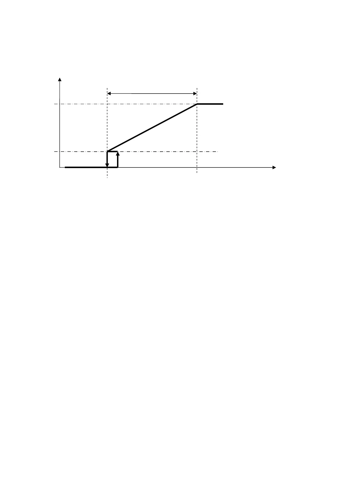
When the temperature reaches the FC setpoint and stays below it for more than PS10 seconds, the free-cooling is deactivated; the step
indicated in the diagram, of hysteresis PS08 (default 0.5°C), re-enables the free-cooling and the ramp (if the ON mode is maintained
for more than PS10 seconds).
When the regulation of the free-cooling is on the ramp, the call of the steps of the compressors is inhibited; when the temperature
reaches the upper limit of the proportional band and stays in that state for at least PS10 seconds, it enables the call of the compressor
steps by action of primary regulation.
The fan can also be ON/OFF type.
Depending on the configuration of parameters PG13 and PG11 the free-cooling can behave in different ways:
PG13=0: SINGLE AIR CIRCUIT
In the event of single condensation (PG11=1), with free-cooling active, the condensation fan will be controlled by the
above-mentioned regulation based on the input temperature. After a load increase, the compressors are turned on then the
regulation of the fan will go to condensation control and remain this way until at least one compressor is active in the
relevant circuit.
In this configuration, the fan used is unique and it is that referred to in circuit 1. This fan will handle condensation and free-
cooling (any free-cooling coil must be put in this position).
In the case of separate condensation (PG11=0), a circuit normally regulates the condensation, while the other
condensation fan is regulated with the above-mentioned free-cooling regulation.
In this configuration the fan used exclusively for condensation is the fan of circuit 2. The fan of circuit 1 will handle
condensation of the relative circuit and of free-cooling if the conditions subsist (any free-cooling coil must be put in this
position).
PG13=1: SEPARATE AIR CIRCUIT
In the case of single condensation (PG11=1), or in the case of separate condensation (PG11=0) having two
independent air circuits there is no need to make any distinction; the behaviour is identical. In this situation it makes sense to use
parameter PS05 (enablement of pre-cooling with compressors):
• PS05 = 0. If at least one compressor is on, the free-cooling is disabled, otherwise normal ramp regulation follows.
• PS05 = 1. If there is at least one compressor on, the free-cooling ramp is forced to the maximum value (100% or other
value set in parameter PS04), otherwise normal ramp regulation follows.
The condensation fans are independent from free-cooling.
To activate the fan associated to free-cooling you must also set the associated analogue output.
T. Regulation

 Loading...


