EVCO S.p.A. EVFTFT618 | Installer manual ver. 2.2 | Code 144FTFT618E224
Page 9 of 62
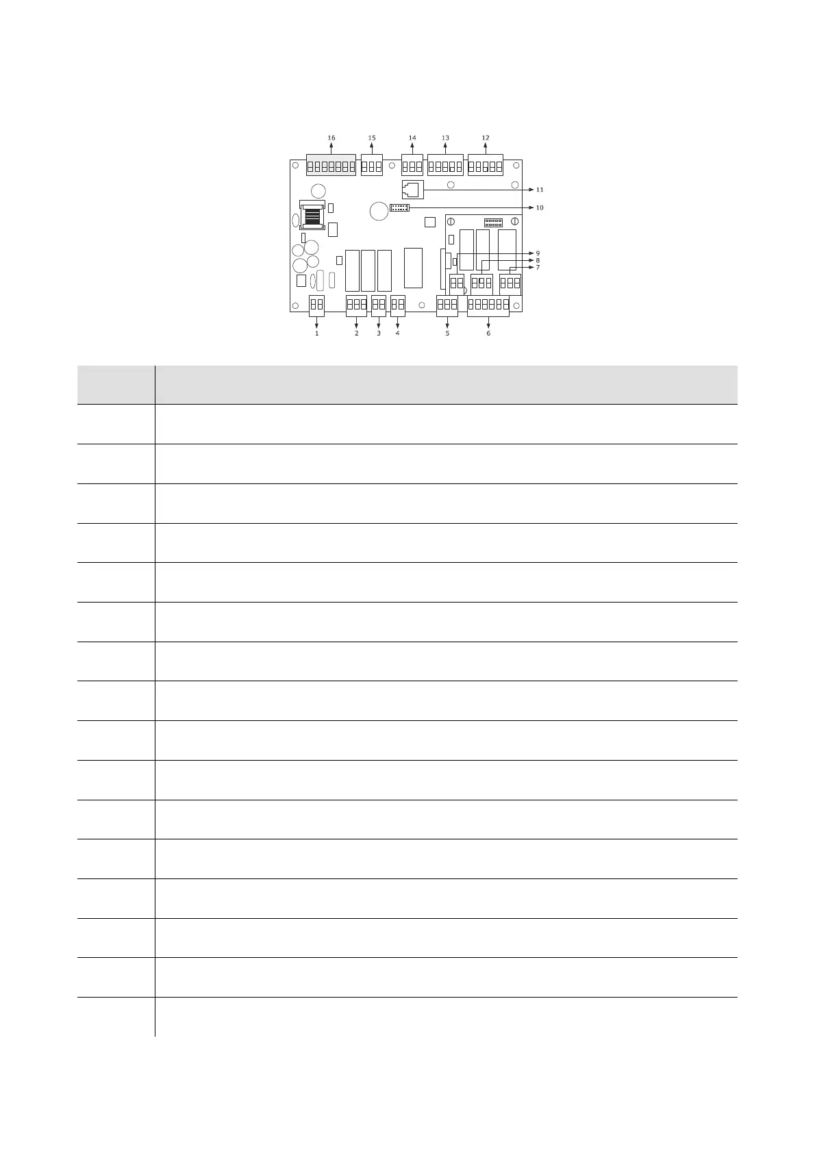
2.2 Description of the control module
The following drawing illustrates the aspect of the EVFTFT818 control module.
The following table illustrates the meaning of EVFTFT618 control module parts.
Part Part
1 power supply
2 digital outputs K3 and K4
3 digital output K2
4 digital output K1
5 digital output K5
6 digital inputs
7 digital output K6
8 digital outputs K7 and K8
9 reserved
10 reserved
11 reserved
12 Not used
13 analogue inputs (cabinet probe, evaporator probe and condenser probe)
14 Humidity probe
15 PWM analogue output
16 communication port with the user interface (signal and power supply)
For further information, see the next chapters.