EVCO S.p.A. EVFTFT618 | Installer manual ver. 2.2 | Code 144FTFT618E224
Page 39 of 62
13 Parameters
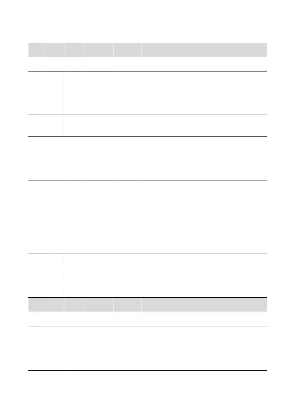
Par. Min. Max. Unit Default Analogue inputs
CA1 -25 25 °C 0 offset cell probe
CA2 -25 25 °C 0 offset evaporator probe
CA3 -25 25 °C 0 offset condenser probe
CA4 -25 25 %r.H. 0 humidity probe offset
P0 0 1 - - - - 1
probe type
0 = PTC
1 = NTC
P2 0 1 - - - - 0
temperature unit of measurement
0 = °C
1 = °F
P3 0 1 - - - - 1
enabling the evaporator probe
0 = disabled
1 = enabled
P4 0 1 - - - - 0
enabling the condenser probe
0 = disabled
1 = enabled
P5 0 60 Min 15
duration of a power supply cut-off during a higher cycle at
which a cycle is interrupted (see also P6)
P6 0 2 - - - - 1
behaviour of the instrument on power supply restore
0 = the cycle will be interrupted
1 = the cycle will be re-started
2 = the cycle will be restarted if the duration of interruption
has been less than parameter P5
P7 0 P8 %r.H. 0
humidity transducer low calibration limit (corresponding to
4mA)
P8 P7 100 %r.H. 100
humidity transducer high calibration limit (corresponding to
a 20mA)
P9 0 250 ds 5
delay displaying temperature variation detected by the
probes
Par. Min. Max. Unit Default Cooling regulator
rC0 1 15 °C 2 differential of the parameters rC3, rC4, rC5
rC1 -99 rC2 °C -20
minimum set-point that can be set for the lock, storage and
manual cooling phases
rC2 rC2 99 °C 20
maximum set-point that can be set for the lock, storage
and manual cooling phases
rC3 0 10 °C 1
cooling neutral area value for the block, storage and
manual cooling phases
rC4 0 10 °C 1
cooling neutral area value for the recovery, proving and
manual heating phases