24 NexLog Recorder User Manual v2.2.0
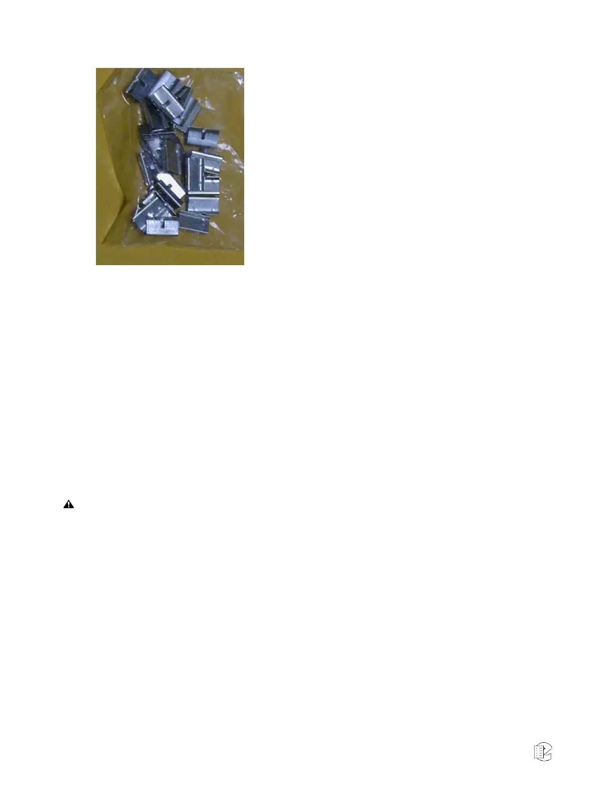
Bridging Clips
The right side (nearest the connector) has each column
connected to an associated connector pin-pair so that the
top row is connected to pin 1, the next row to pin 26, the
third to pin 2, etc. Thus, adjacent vertical rows form one
signal pair.
When you connect the first telephone line, you just start
at the top and connect the wire pair to the first two rows
on the left. The next wire pair would go to the next two
rows down, on the left.
Finally, to connect the telephone line to its associated
recorder input, slip two bridging clips over the two center
contacts in each row.
The purpose of the punch block system is to centralize your connections, as well
as to provide a clean way to isolate the telephone or radio system from the
recorder, should it become necessary. The components can be isolated by
removing clips, rather than removing wires.
2.4.10. Connecting Digital PBX Stations that are to be Tapped
NOTE: For tapping digital PBX telephones and T1/E1 circuits, maximum cable
lengths are extremely important, and can be different for different makes &
models of telephone systems. Contact Eventide technical support for digital-tap
cable length information for your particular digital phone system or T1/E1
circuits.
This section applies to units equipped with one or more Digital PBX Station
tapping Boards. If you are not sure this board is installed, check the printed
back-panel diagram that was packed with your recorder.
WARNING To reduce the risk of fire, use only 26 AWG or larger telecommunication wire.
The Digital PBX Station tapping Board handle interfacing to certain Digital PBX
Station makes and models (check with Eventide for compatibility). The number
of channels per board will vary depending on which is ordered. Eventide sells 8,
16, and 24 channels versions of the Digital PBX Station tapping Board.
A mating connector is provided for each board unless a Quick Install Kit has
been ordered (see Section 2.4.9. The Optional Quick Install Kit. The connector has
two rows of contacts. One row is numbered 1 through 25, and the other row is
numbered 26 through 50. Numbering is such that pin 1 is opposite 26, and 25
is opposite 50. For most Digital PBX systems (except Mitel Supersets, Avaya
Index phones, and ROLMphones), each Digital PBX Station requires two wires.
Eventide offers a Quick Install Kit that, besides pulling together the parts you
will need for a convenient installation, brings Channel 1 to the white-blue pair
(see Section 2.4.9. The Optional Quick Install Kit)