28
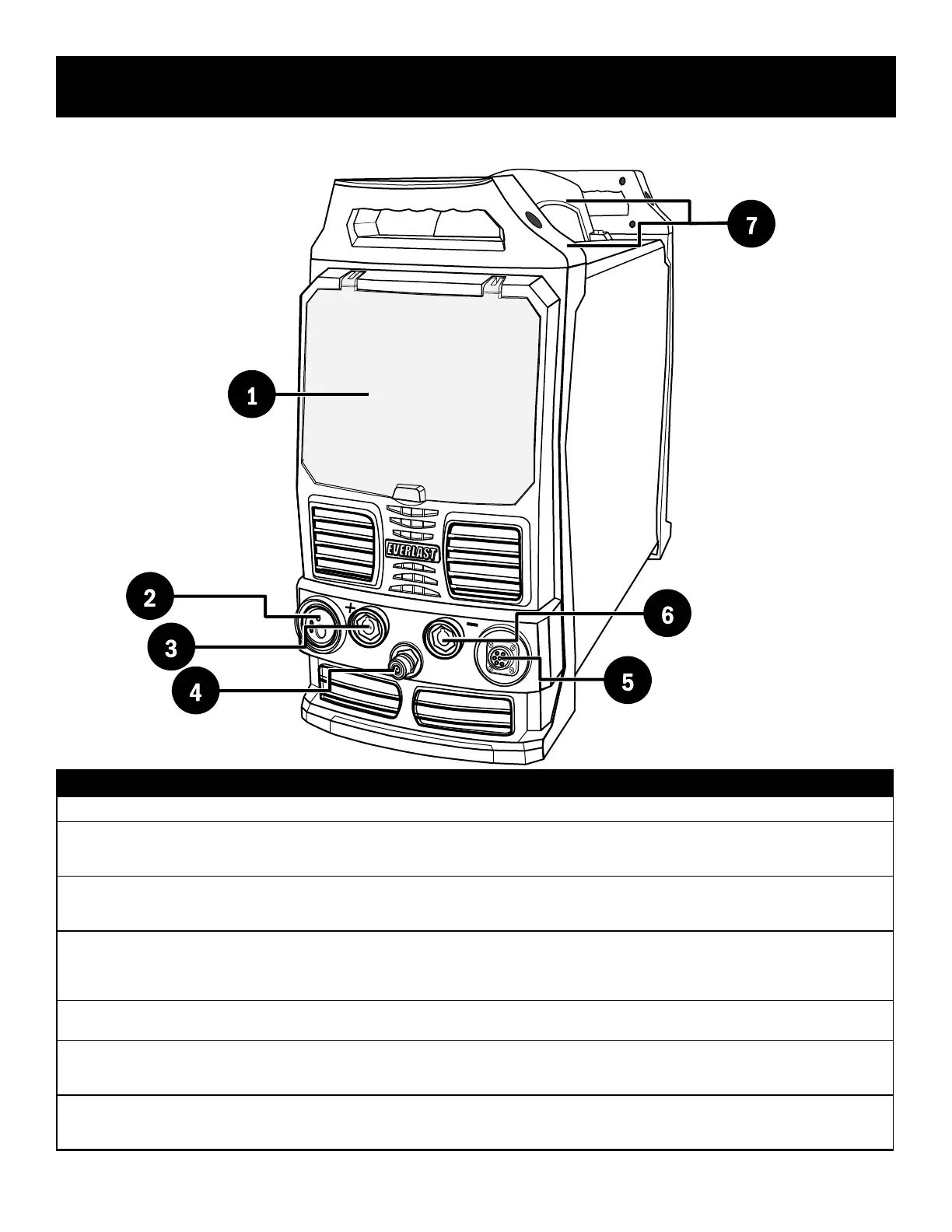
Component Identification and Explanation
1
2
3
5
6
7
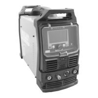
# Component Identication Function/Component Note
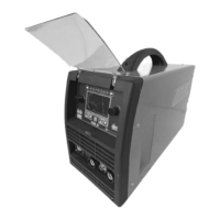
1. Protective Cover Keep cover down and in place during welding activities and while in storage.
2.
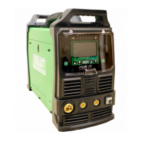
Euro-Style Quick MIG Connector
(Only one gun may be connected at a time.)
Connect the MIG gun to this connector.
Connect the Spool Gun to this connector.
Connect the Push-Pull Gun to this connector.
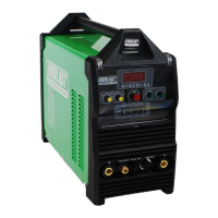
3.
Positive Terminal (+)
(DINSE 35/50mm
2
Type, 1/2” nominal dia.)
Connect the work clamp to this terminal for TIG welding.
Connect the work clamp to this terminal for Gasless Flux-Cored Welding.
Connect the Stick electrode holder to this terminal for most DC Stick Welding.
4.
TIG Torch Shielding Gas Connection
(Quick Connect, 9mm tube Type 21)
The gas line from the TIG torch is connected to the quick coupler. The sleeve/collar of the coupler is normally
held back until the male torch tting is inserted until it clicks in place. The coupler should slide forward to capture
and hold the connector. To release the torch tting, manually slide the outer collar/sleeve back.
Ref. EV-9MM-B-QUICK CONNECT-STDSET or 21KATS09MPX
5.
7 Pin Control Connector
(5/8” Type GX16-7)
All torch switch and foot pedal connections attach at this point. (One at a time.)
Ref. EV-PANA7-625-PLUG
6.
Negative Terminal (-)
(DINSE 35/50mm
2
Type, 1/2” nominal dia.)
Connect the work clamp to this terminal for MIG operation. (Not for Gasless Flux-Cored use.)
Connect the TIG torch to this terminal for all TIG welding applications including AC.
Connect the work clamp to this terminal for most DC Stick welding applications.
7.
Handles The handles are packed separately in the box and are not installed. Installation is recommended, but the handles
are designed to be removeable for low clearance or for some permanent mount applications. Be sure to reinstall
screws in the cover and panel if the handles are to be removed or not installed.
Front Panel View
4
 Loading...