32
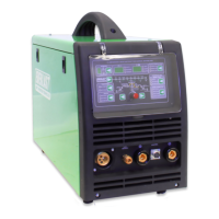
GENERAL INFORMATION ON SETUP AND USE.
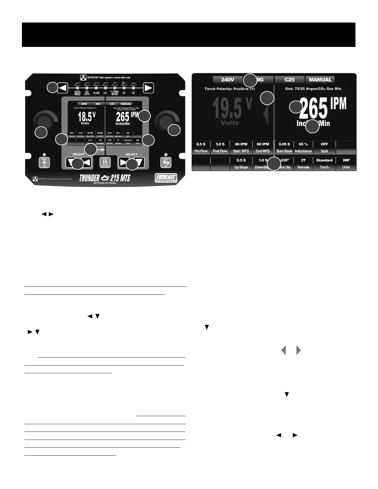
Selecting the Process.
At the top of the panel (1) use the process selector buttons to select the
desired welding or cutting process. Use either the right or left arrow direc-
tional ( ) buttons to advance to the next process. Pressing the left or
right arrow button too quickly multiple times in succession may cause the
LED to appear to skip a process. Advance through the processes at a mod-
erate, deliberate pace. If desired welding process is accidentally passed or
skipped over, instead of cycling back through all the processes, use the
opposite directional arrow button to scroll back to the desired process
rather than scrolling all the way through again.
Navigating the On-Screen Menu.
The LCD screen is divided visually into a right and left half (2) by a vertical
green bar on screen and black line above and below the screen. The left
half side is controlled by the left side panel controls. The right half is con-
trolled by the right side panel controls. The left side left (3) left pointing
and down pointing arrows ( ) are used to navigate the left half of the
screen and the right side (4) right pointing and down pointing arrows
( ) are used to navigate the right half of the screen. The left and right
control knobs (5,6) are used to increase or decrease the selected parame-
ter value of that side or to change the status of a function of the related
side. The menu is also divided horizontally into 2 functional areas. 1) The
top tier, or main display/default parameter display area, and the two lower
tiered rows of parameters and functions.
There are two types of information located on-screen in the two lower
tiered rows (7,8) of the on-screen menu: Parameters and Functions. Func-
tions are menu items that may change in status, such as ON/OFF, or Gun
Selection. Parameters are menu items that change in value throughout a
range such as pre-flow time or inductance percent. Some selectable items
on the menu screen serve both as functions and parameters. For example,
the Spot weld function can be set to “OFF”. That indicates the status of the
function. But when selected and the control knob is rotated, and the status
is changed to “ON”, the function automatically changes to represent the
parameter value and displays the seconds.
Understanding the Anatomy of the Menu Screen.
Quick Steps to Setting-Up the Welder.
1. The main display in the upper area serves to display the status, or
value of a function or parameter. (1a)
• After startup, while welding or when the unit is not in the adjustment
mode, Voltage is displayed on the left side of the menu screen and
the Wire Feed Speed (IPM or M/M) or Amps on the right side of the
menu screen. These are the default parameters displayed unless the
unit is in adjustment mode and other parameters or functions are
selected for adjustment. These default parameters can be adjusted
simply by turning the relevant side control knob. The display will turn
red to indicate adjustment
• After adjustment is nished and no further adjustment or changes are
made, the unit will re-enter the default mode within approximately 5
seconds and display the Voltage and Wire Feed Speed/Amps.
2. Entering adjustment mode allows the user to make changes to all
functions statuses and parameter values.
• To enter the adjustment mode, press once on the down arrow key
( ) on either the right or left side, depending upon which side the
desired function or parameter is located on. This will turn the main
display on that side red in color, the middle vertical line will turn red
and either a left or right red arrow ( or )will appear to indicate
which side is ready for adjustment. (2a) Alternatively, to enter the
adjustment mode, a slight turn of the control knob will enter the weld-
er into the adjustment mode unless the default displayed is non ad-
justable and displayed in green (TIG/Stick modes).
• Continue to use the down arrow key ( ) to navigate vertically down
to the desired row.
• In TIG and Stick modes, a single press on the down arrow on the left
side will automatically navigate to the rst lower row.
• Use the left or right arrow button ( or ) to navigate over to the
desired parameter or function to highlight for adjustment.
1
7
6
5
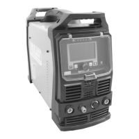
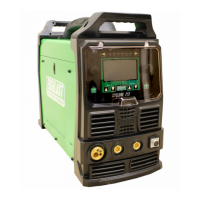
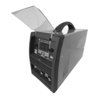
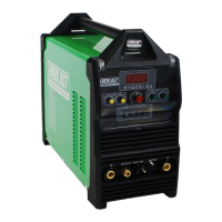
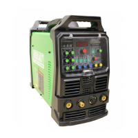
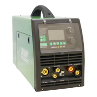
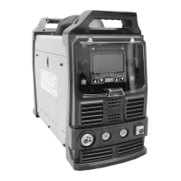
Component Identification and Explanation
2
4
5
3
8
2a
1a
3a
4a
5a
 Loading...