33
• The middle red line will extend to the row and over to the desired
parameter and the selected parameter will be highlighted in red.
3. The control knobs are used to increase or decrease a selected parame-
ter value, or make a status change in a selected function.
• Use the control knob on the side closest to the desired function or
parameter to make changes to status or value.
• When making large changes in value to a parameter, press in on the
control knob while continuing to turn it to make larger increment
changes in value. This will speed up the adjustment process.
Detailed Menu Information and What to Expect During Adjustment
The menu screen utilizes a combination of symbols, words, numbers,
colors and graphical indicators to assist the user in making adjustments. It
is designed to create a fluid, intuitive and easy to understand interface for
the user.
The menu is divided into several basic areas and conveys useful infor-
mation to the user.
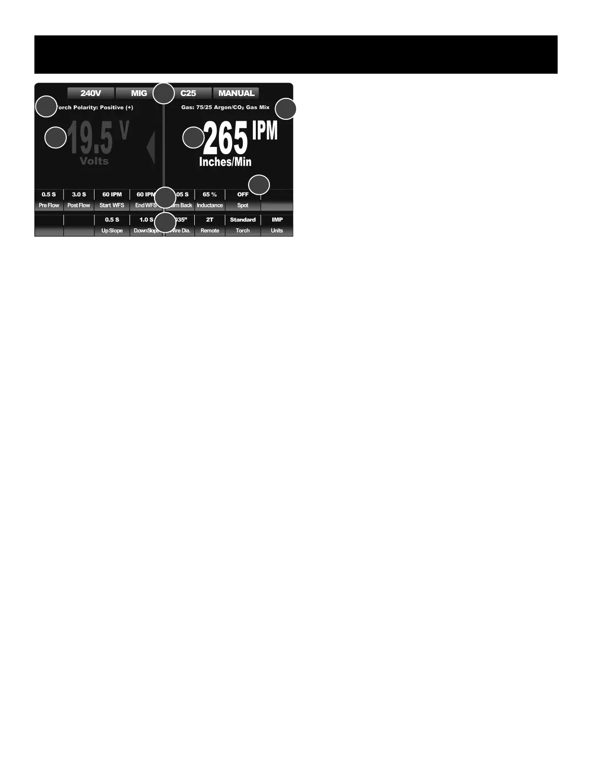
1. Top Information Bar. (1B) This area conveys information to the user
about basic process selection, operating mode, and input voltage.
2. Torch Polarity and Gas Selection Information (2b). This row is in
yellow lettering for contrast. This is area is designed to serve as a
important reminder to the user to check and conrm both gas type
and torch/gun polarity. The gas selection information may change in
Steel MIG mode (C25) depending upon the settings of the unit. At
higher volts and wire speed settings the gas recommendation may
change from 75/25 Ar/CO
2
(C25) to 90/10 Ar/CO
2
(C10).
3. The main display area, or top tiered row (3b). This area on both left
and right sides of the machine will display default Volt and Wire Feed
Speed/ Amp settings unless the adjustment mode is entered into.
During active welding, it will also display the actual measured Volt
and Amp output of the machine. During adjustment, the display will
reflect the chosen parameters and values of the parameters. During
adjustment, the main display area values and parameters will change
color to red. Appoximately 5 seconds after adjustments are completed
the main display area will revert to the default setting and colors.
4. The lower parameter rows/tiers. (4b and 5b) This area displays all the
information related to adjustable parameters and selectable functions
of the unit. In the PowerSet mode, only one line may be displayed
due to the simplied input design.
When a parameter or a function is selected, the screen will display the
value or status of the function in two places:
1) At the top of the screen in the main display area.
2) Just above the selected parameter in the lower rows
The value-based parameters are also accompanied at the top of screen by
the parameter’s unit of measure in an abbreviated exponent form such as
V, S, or % to as a reminder of the value being adjusted. Underneath the
parameter value or function status, the actual name of the selected function
or parameter appears. This redundant arrangement makes the display
easier to read during adjustment and helps to eliminate bottle necks in
navigation.
After adjusting is completed, the machine will default back to the main
adjustment value (Volts, Amps or Inches per Minute) after approximately 5
seconds if no further input is made. The purpose of displaying the value or
status of the lower tiered rows and the upper default value is to provide an
at-a-glance view of all parameters simultaneously on the single screen at
any time during operation. This eliminates the need for pop up menus and
bottle necks in setup while promoting operator awareness of settings.
The screen makes use of colors to indicate condition, mode and status and
serves to aid the user in general in interpreting the on screen information.
1. Green:
• The green color (4b, 5b) of the two lower rows/tiers of boxes indi-
cates normal operation or that the unit is ready for use. The two lower
tiered rows of boxes are normally green, unless the parameter of the
box has been selected for adjustment by the user. Green is used to
indicate a set function status or relay a parameter value to the user.
• Green is used at the top information bar to communicate basic status
information. It is used to conrm the mode and basic operating infor-
mation. If the Voltage box in the information bar turns yellow, this
indicates the unit is operating on 120V. This is to serve as a reminder
that output is limited in 120V and some settings may not have a full
range of adjustment or selection.
• When the large numbers turn green in the top, main display area, this
indicates the value cannot be adjusted. However, it is communicating
an important measured value, such as TIG or Stick welding Voltage
and OCV.
2. Gray:
• Gray, blank areas in the lower rows of boxes are non-selectable are-
as. These emptied boxes can be ignored and no function is assigned
to them in the current menu conguration or process.
Component Identification and Explanation
1b
5b
3b
4b
6a
2b
3b
2b
 Loading...