7700FR/7800FR MultiFrame
7800TR-32x24 Modular Tally Router
Page -
ii Revision 1.2
4.3.3 Configuring the GPO ............................................................................................... 25
5 OPERATION ............................................................................................................................... 26
5.1 QUARTZ REMOTE CONTROL PROTOCOL ..................................................................... 26
5.2 MAGNUM INTEGRATION .................................................................................................. 28
5.2.1 MAGNUM-TALLY License ....................................................................................... 28
5.2.2 Adding the Tally Router to MAGNUM ...................................................................... 29
5.2.3 Setting up the MAGNUM Tally Grid ......................................................................... 30
6 UPGRADING THE FIRMWARE .................................................................................................. 31
6.1.1 Performing a Firmware Upgrade with VistaLINK® Pro ............................................ 31
6.1.2 Performing a Firmware Upgrade through the Card Edge Serial Port ....................... 32
Figures
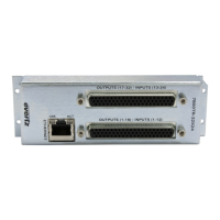
Figure 1-1: 7800TR-32x24 with Accompanying Rear I/O Module (Rear plate) ................................................ 1
Figure 3-1: 7800TR-32x24 Rear Plate .............................................................................................................. 5
Figure 3-2: Card Edge LEDs and Serial Port .................................................................................................... 7
Figure 3-3: 7700 Upgrade Cable Picture (WA-S76) ......................................................................................... 8
Figure 3-4: Rear Plate 62-pin D-Sub Connectors Pinouts .............................................................................. 11
Figure 3-5: Rear GPI Input Schematic ............................................................................................................ 13
Figure 3-6: Rear General Purpose Output Circuit Diagram (Dry) ................................................................... 14
Figure 3-7: Optional 7800TR-BHP Bulkhead Panel ........................................................................................ 18
Figure 3-8: 7800TR-BHP GPO in Wet Mode Circuit Diagram ........................................................................ 18
Figure 3-9: 7800TR-BHP GPO in Dry Mode Circuit Diagram ......................................................................... 19
Figure 3-10: 7800TR-BHP GPI in Wet Mode Circuit Diagram ........................................................................ 19
Figure 3-11: 7800TR-BHP GPI in Dry Mode Circuit Diagram ......................................................................... 19
Figure 4-1: VistaLINK® Pro Version Information ............................................................................................ 22
Figure 4-2: VistaLINK® Pro Configuration View ............................................................................................. 23
Figure 4-3: VistaLINK Pro GPI Settings Tab ................................................................................................... 25
Figure 4-4: VistaLINK Pro GPO Settings Tab ................................................................................................. 26
Figure 5-1: Magnum License Management Screen ........................................................................................ 28
Figure 5-2: Magnum Devices View ................................................................................................................. 29
Figure 5-3: Adding a Tally Router Device to Magnum .................................................................................... 29
Figure 5-4: Magnum Tally Grid Configuration View ........................................................................................ 30
Figure 6-1: VistaLINK® Pro Upgrade Firmware Dialog .................................................................................. 31
Tables
Table 3-1: Standard 8-pin Modular Connector Wiring Color Codes ................................................................. 6
Table 3-2: 7700 Upgrade Cable Wiring (WA-S76) ........................................................................................... 8
Table 3-3: COM Port Settings ........................................................................................................................... 8
Table 3-4: Command Line Interface Commands .............................................................................................. 9
Table 3-5: Rear GPI Input Electrical Specifications ........................................................................................ 13
Table 3-6: Rear General Purpose Output Electrical Specifications ................................................................ 14
Table 3-7: Wet Power Source Selections ....................................................................................................... 15
Table 4-1: VistaLINK® Pro Configuration Tabs .............................................................................................. 24