HD2014, HD2012, HD2011 Video Passport
TM
1RU Multi-Path Video Converter, Frame Synchronizer and Decoder
INSTALLATION Revision 0.1 Page 2-1
2. INSTALLATION
2.1. REAR PANEL OVERVIEW
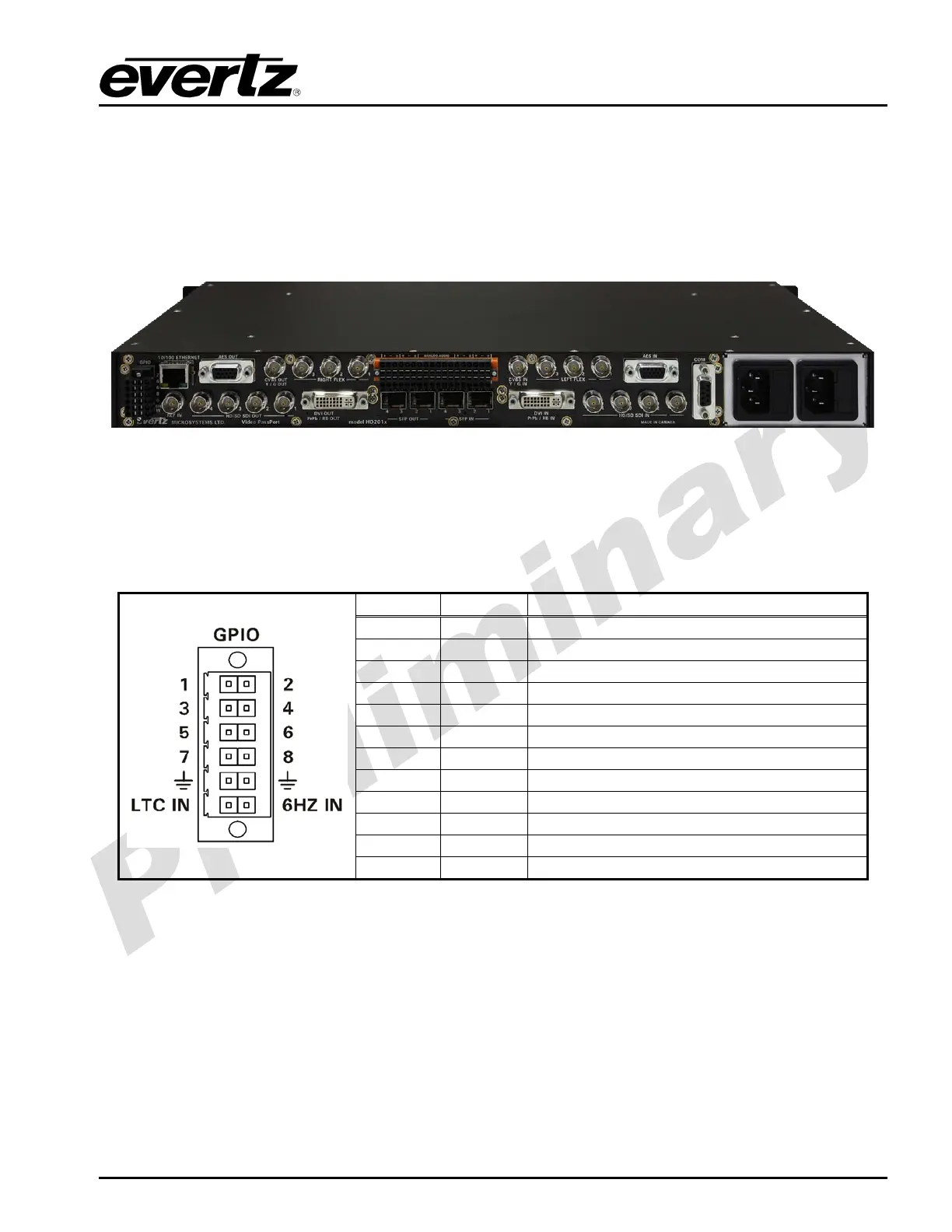
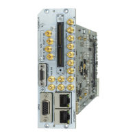
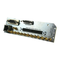
The rear panel of the HD201x Video PassPort series is shown in Figure 2-1. The following sections will
give an overview of each connection and their function including any relevant pin-out information.
Figure 2-1: Rear View of HD2014
2.1.1. GPIO (General Purpose Input/Outputs) Connections
The HD201x series supports eight configurable GPIOs. Table 2-1 describes the pin-out information for
the GPIO removable terminal block connector.
PIN # Name Description
1
GPIO1 General Purpose Input/Output #1
2
GPIO2 General Purpose Input/Output #2
3
GPIO3 General Purpose Input/Output #3
4
GPIO4 General Purpose Input/Output #4
5
GPIO5 General Purpose Input/Output #5
6
GPIO6 General Purpose Input/Output #6
7
GPIO7 General Purpose Input/Output #7
8
GPIO8 General Purpose Input/Output #8
9
GND Signal Ground.
10
GND Signal Ground.
11
LTC IN LTC IN Input (not used at time of writing)
12
6HZ IN 6HZ In Input (not used at time of writing)
Table 2-1: Pin out for General Purpose Inputs/Outputs