128
ELECTRICAL AND IGNITION
CHARGING SYSTEM TESTS
Start the outboard and run it at approximately
5000 RPM. Use the variable load tester to draw
the battery down at a rate equivalent to the sta-
tor’s full output.
• The ammeter should indicate nearly full output,
Approximately 25 A @ 5000 RPM.
Decrease the battery load toward 0 A.
• Ammeter should show a reduced output. As the
current draw decreases, the battery voltage
should stabilize at approximately 14.5 V.
• If results vary, check stator BEFORE replacing
the EMM. See STATOR TESTS on p. 126.
55 V Alternator Circuit
Check battery ground cable for continuity.
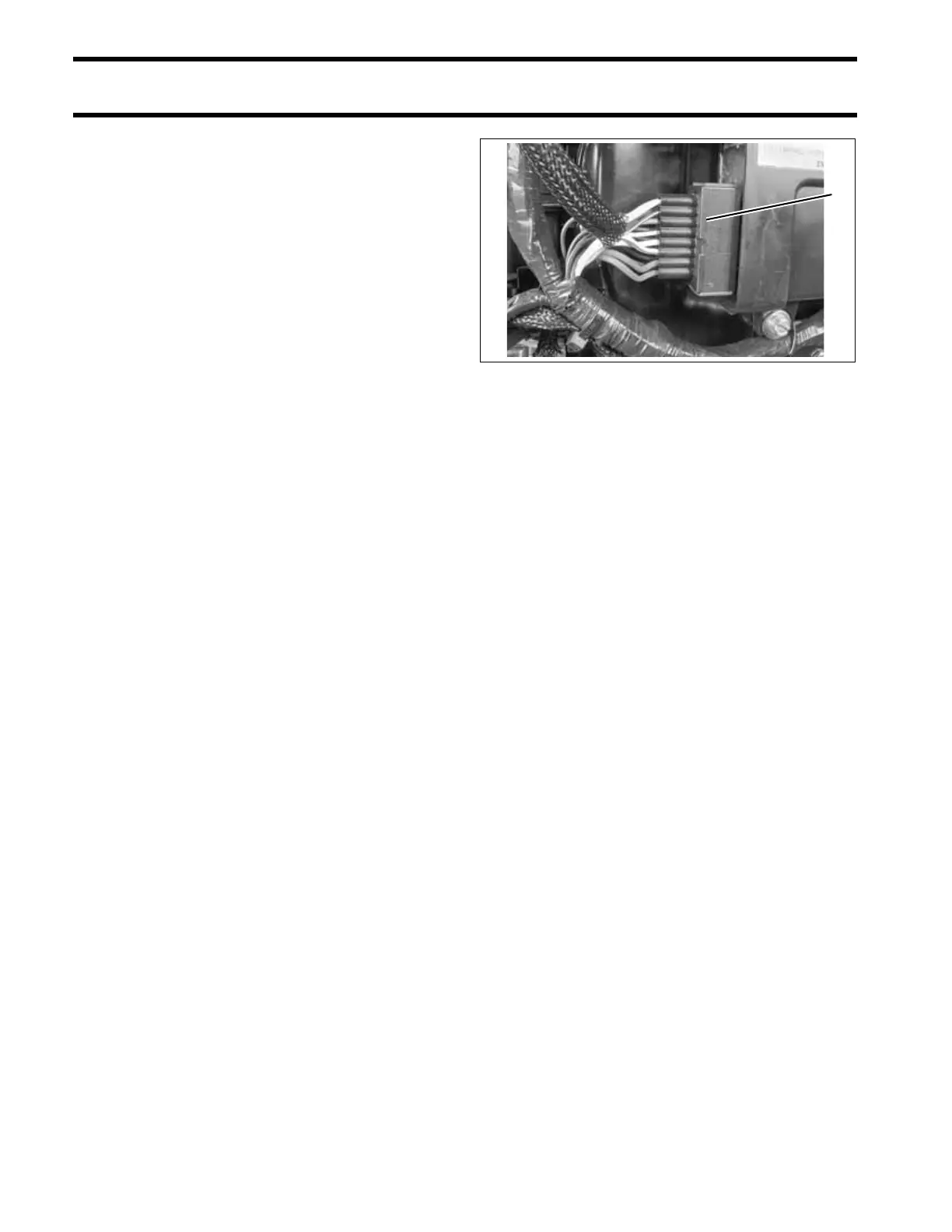
With the key switch ON, check battery voltage at
battery (12 V), then check voltage on white/red
wires at J2 connector of EMM. Use Electrical Test
Probe Kit, P/N 342677 and a multimeter set to
read 55 VDC. Voltage at EMM connector should
be 0.5 to 1 V less than battery.
With outboard running at 1000 RPM, voltage on
white/red wires should increase to 55 V.
Voltage readings at a specific speed (RPM)
should be steady.
If there is any other reading, refer to STATOR
TESTS on p. 126. Inspect the stator wiring and
connections. Inspect the capacitor wiring, connec-
tions, and capacitor. Repair the wiring or replace a
faulty capacitor, stator, or EMM.
1. J2 connector of EMM 002291
1
 Loading...