228
POWERHEAD
POWERHEAD INSTALLATION
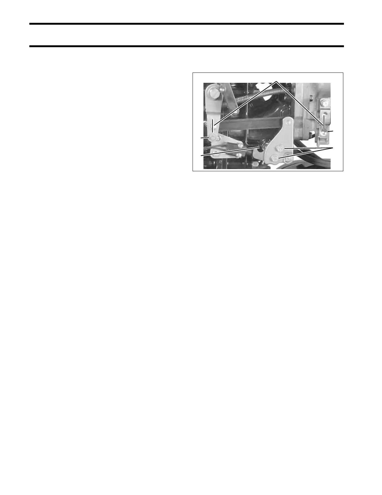
Shift Linkage Adjustment
Adjust shift linkage as follows:
• Loosen adjustment screws on shift lever.
• Be sure that ball is centered in detent assembly.
• Adjust shift lever so that the screw hole in shift
rod lever lines up with the hole in the gearcase
shift rod when gearcase is in neutral.
• When correctly adjusted, the shift lever will be
parallel with the vertical line of the outboard,
and the distance between the shift lever pin and
the center of the shift cable trunnion pocket
should be approximately 7 in. (17.8 cm).
IMPORTANT: The shift rod height is the most
critical of these adjustments and should not be
moved during this procedure. Refer to SHIFT
ROD ADJUSTMENT on p. 266.
• Tighten adjustment screws to 60 to 84 in. lbs. (7
to 9.5 N·m).
1. Adjustment screws
2. Shift detent assembly
3. Shift lever pin
4. Trunnion pocket
5. 7 inch dimension
002125
5
4
1
3
2
 Loading...