87
ENGINE MANAGEMENT MODULE (EMM)
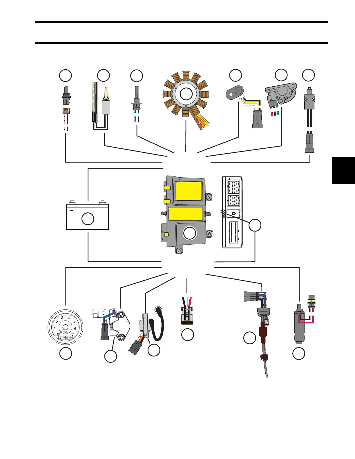
EMM INPUTS AND OUTPUTS DIAGRAM
5
EMM INPUTS AND OUTPUTS DIAGRAM
11
12
13
+
2
CB
A
INPUTS
OUTPUTS
6
4
8
9
10
2
7
A
B
5
3
12
1
21
J1-B
J1-A
J2
1
3
2
1
14
15
1
2
3
4
16
002043T
1. Engine Management Module (EMM)
2. Battery (12 volt)
3. Stator
4. Crankshaft Position Sensor (CPS)
5. Throttle Position Sensor (TPS)
6. Neutral Switch
7. Air Temperature Sensor (AT)
8. Oil Pressure Switch (component of 11)
9. Engine Temperature Sensor
10. Fuel Pump (high pressure)
11. Oil Injection Pump and Manifold
12. Ignition Coil
13. Fuel Injector
14. Tachometer/SystemCheck Gauge
15. Diagnostic Connector
16. LED Indicators

 Loading...