217
POWERHEAD
POWERHEAD ASSEMBLY
11
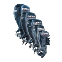
IMPORTANT: Be sure gap of ring fits squarely
around dowel pin.
IMPORTANT: Before continuing, make sure
that all Gel-Seal II has been removed from the cyl-
inder block and crankcase mating flanges. If
traces of hardened Gel-Seal II are left, main bear-
ings could be misaligned. Refer to CYLINDER
BLOCK CLEANING on p. 210.
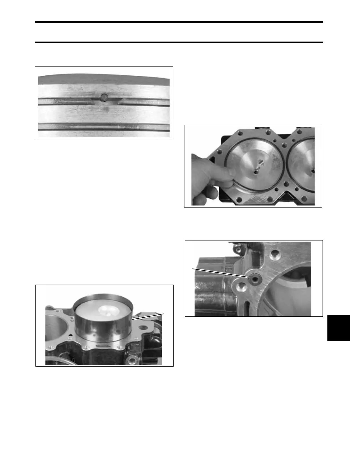
Coat pistons, rings, cylinder walls, and Ring Com-
pressor, P/N 336314, with outboard lubricant.
Center connecting rod in piston and locate piston
rings on dowel pins. Place appropriate ring com-
pressor on piston.
Slide piston and rod assembly into the correct cyl-
inder, as marked during disassembly. Guide con-
necting rod through cylinder block to avoid
scratching cylinder wall.
Cylinder Head Installation
Install a new thermostat seal in cylinder head with
side marked “TO CYL HEAD” facing toward ther-
mostat.
Refer to THERMOSTAT SERVICING on p. 196
before installing cylinder head.
Lightly lubricate new cylinder head O-rings with
Triple-Guard grease and install in cylinder head.
Apply soapy water to water dam and insert into
block.
002048
1. Ring compressor 002059
1
002061
1. Water dam 002062
1
 Loading...