120
ELECTRICAL AND IGNITION
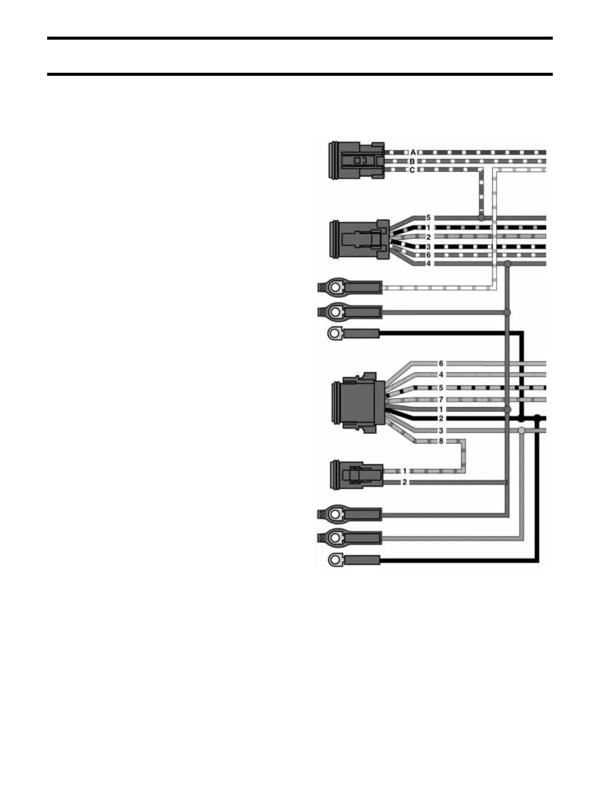
DASH CONNECTIONS, INSTRUMENT HARNESS
DASH CONNECTIONS,
INSTRUMENT HARNESS
3-pin connector – Connect to trim switch located
in the handle of the remote control or to trim
switch mounted on the boat dash.
6-pin connector – Connect to a pre-wired remote
control or to a dash-mounted key switch.
Black, purple, white/tan wires – Connect to the
trim gauge.
8-pin connector – Connect to a 2 in. System-
Check gauge or to a 3 1/2 in. SystemCheck
tachometer.
2-pin connector – Must connect to the warning
horn in all installations.
Black, purple, gray wires – Connect to a con-
ventional tachometer when a SystemCheck
tachometer is not used.
Instrument Harness Diagram (MWS) DRC6165R