13
X EVINRUDE® ICON™ CONCEALED SIDE MOUNT REMOTE CONTROL USER’S GUIDE
ICON NETWORK SPECIFICATIONS AND INFORMATION
Specifications
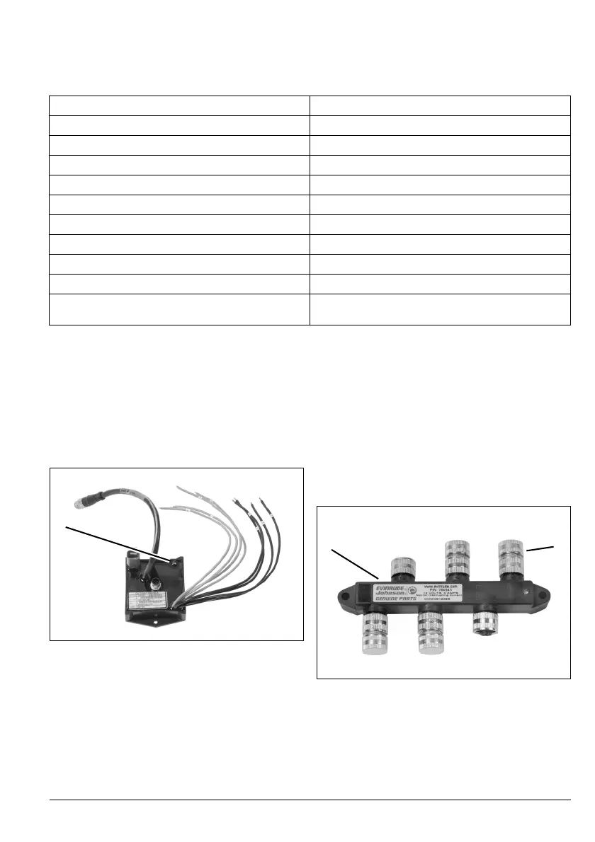
ICON Gateway Module
The ICON gateway module provides network
data to the NMEA 2000 network and I-Com-
mand gauges.
The gateway module receives power from the
network power cable. When the gateway is
powered and receiving data from the network
the LED on the gateway module turns ON.
The gateway module provides fuel level mon-
itoring for up to four fuel tanks when connect-
ed to fuel level senders.
ICON Network Hubs
ICON network hubs are used to connect buss
cables to remote controls, gateway module,
master power/key switch and to other devices
on the network.
Two hubs MUST be installed in the ICON net-
work. See ICON System Diagram on
page 18.
Protective covers must be used to seal un-
used connections.
Supply Voltage (Boat System)
9 to 18 VDC
Operating Voltage (ICON Control Network)
5 VDC
Engine Control
1, 2, 3, 4, or 5 outboards
Reverse Polarity Protection
Continuous
Fuse, Network
10 Amp, ATO Type, P/N 967545
Fuse, Master Power/Key Switch
3 Amp, ATO Type, P/N 764538
Fuse, Electronic Servo Module
30 Amp, Minifuse Type, P/N 5032630
Fuse, Accessory Power Relay Kit
10 Amp, Minifuse Type, P/N 514766
Network Interface
Proprietary, based on NMEA 2000 standard
Operating Temperature Range
-13° to 167° F (-25° to 75° C)
Maximum Current Draw
(Master Power/Key Switch turned OFF)
10µA
1. LED on gateway module
007913
1
1. ICON network hub
2. Protective cover
007945
1
2