34000 Autry Street, Livonia, MI 48150 • 800.968.5530 • Fax 734.419.0209 • www.hamiltonengineering.com • LIT91127 REV 3/09
F. SETTING THE MINIMUM LOAD
Set the minimum load once the maximum load has been set, turn the knob until the minimum RPM setting
has been reached. In order to set or adjust the minimum load, turn the screw [2] for the minimum setting (rst
remove the protective cap). Turn the screw clockwise to increase or counter clockwise to decrease the CO2
percentage. On the HW 599, you only are allowed to set the gas valve at the right side; the left gas valve is set
by the manufacturer. See Section H for special instructions on replacing both gas valves in a model 599.
• If the measuring process takes more than 40 minutes, the appliance will return to the automatic mode.
If so required, press the Service button another time.
• When you are done setting the valve, press the Service button again to return to normal run mode
Please do not forget to replace the protective cap on the gas valve.
Page 13 of 50
If necessary, turn the adjusting slot [1], which sets the high re performance, either counterclockwise to increase
the CO2 percentage or clockwise to reduce the CO2 percentage, as shown in Figures 3-2 and 3-3, Page 11.
Appropriate CO2 percentages are shown in Table 3-3 on the previous page.
Do not forget to place the knob, labeled with “Setpoint,” at the proper temperature value when done.
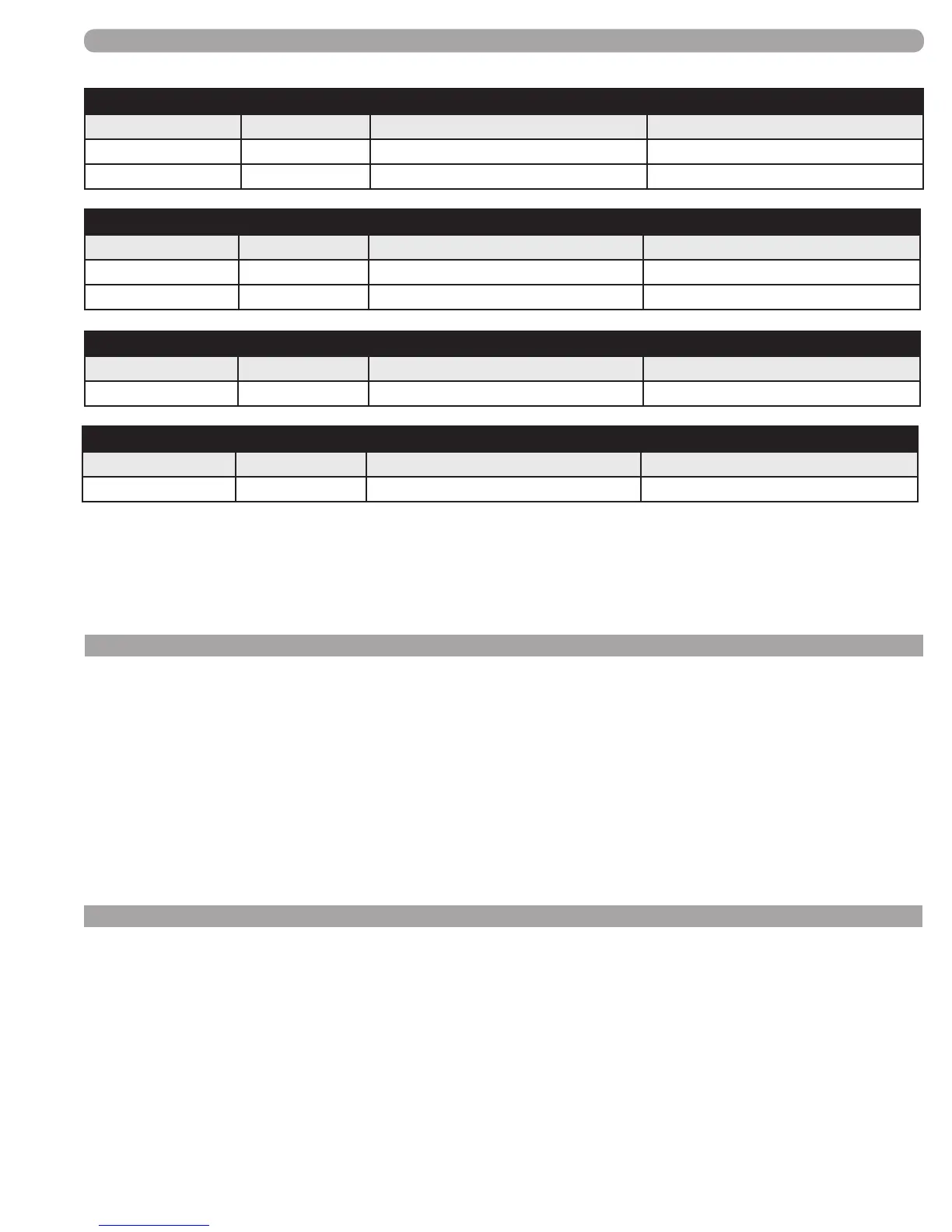
Last 4 digits of serial number
HWD 299
First Week Last Week Maximum rpm Minimum rpm
49--06 01--08 6300 1890
02--08 current 6300 1575
Last 4 digits of serial number
HWD 399
First Week Last Week Maximum rpm Minimum rpm
24--05 current 6200 1798
Last 4 digits of serial number HWD 599
First Week Last Week Maximum rpm Minimum rpm
24--05 current 5700 1596
Last 4 digits of serial number
HWD 199, HWD 199.1, HWH 199, HWH 199.1, HWH 199.8
First Week Last Week Maximum rpm Minimum rpm
24--05 48--06 5900 1711
49--06 current 6500 1755
GAS CONNECTION
If the appliance is to be converted in the eld for using Propane (LPG), the following steps must be taken:
• Turn screw [1] (Figure 3-2, page 11) .75 of a full turn (270°) on models HW 79/199.1,three quarters of
one turn (270°) on models HW 199/299 and 1 full turn (360°) on model HW399
• On model HW599 (Figure 3-3, page 11) turn screw on left hand valve closed (clockwise) and turn right
valve 1.75 of a full turn clockwise.
• Run the appliance. If the burner does not ignite after four starting efforts, turn the screw [1] one half turn
back (180°) (counter clockwise).
• After conversion, follow the steps in Sections E and F for setting the maximum and minimum loads,
using the LP gas values shown in Table 3-3, page 12.
G. GAS CONVERSION