34000 Autry Street, Livonia, MI 48150 • 800.968.5530 • Fax 734.419.0209 • www.hamiltonengineering.com • LIT91127 REV 3/09
GENERAL INFORMATION/ELECTRICAL
WARNING
The EVO is certied as an indoor appliance. Do not install the EVO outdoors
or locate where it will be exposed to freezing temperatures. This includes
all related piping and components. If the EVO is subjected to ood water or
submersed in water, the EVO must be replaced.
NOTICE
Condensation Removal: This is a condensing, high efciency appliance, there-
fore condensation removal must be addressed to avoid damage to surrounding
area or appliance. See Part 4, Section F for Condensate Requirements (pg.20).
D. PRESSURE RELIEF VALVE
This unit is supplied with a relief valve sized in accordance with ANSI/ASME Heater and Pressure Vessel Code,
Section IV. The relief valve is installed near the hot water outlet. If the valve supplied is replaced, the pressure
rating of the valve must not exceed the listed working pressure of this appliance, and must be rated to the proper
BTU/hr capacity of the water heater. Do not, under any circumstances, thread a cap or plug into the relief
valve! Explosion, serious injury or death may result! To prevent water damage, the relief valve piping must
be directed to the oor or an open drain, but not connected directly. There must be a 6” space between the outlet
of relief valve piping and drain or oor. Do not hook up to drain system directly without an air gap. Protect from
freezing. Place no other valve between the relief valve and the unit. Do not install any reducing couplings or other
restrictions in the discharge line. The discharge line must allow complete drainage of the valve and line. Manually
operate the relief valve at least once a year.
Also, care must be exercised when choosing the location of this appliance, where leakage from the relief
valve, leakage from related piping, or leakage from the tank or connections, will not result in damage to the
surrounding areas, or to the lower oors of the building. A water heating appliance should always be located in an
area with a oor drain or installed in a drain pan suitable for water heating appliances. Under no circumstances,
shall Hamilton Engineering, Inc. be held liable for any such water damage whatsoever.
SERVICE
RESET
LO
TEMPERATURE
CH
OFF
ON
- +
INNOVATIVE CONDENSING T ECHNOLOGY
By Hamilton Engineering, Inc.
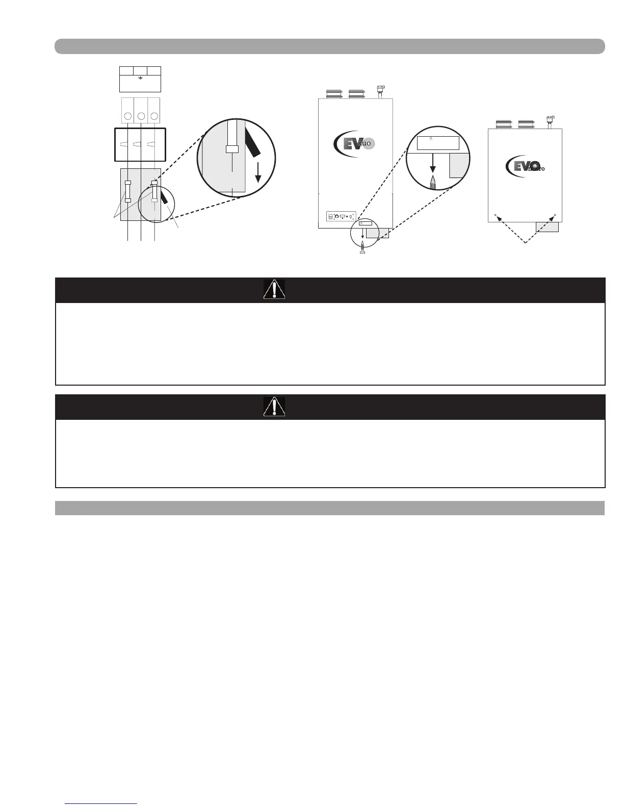
WARNING!
#1 Turn off power
to unit
#2 Remove bottom
screw(s)
WARNING!
Before removing screw and opening front cover,
main power supply must be disconnected (shut off).
HIGH VOLTAGE - RISK OF ELECTRICAL SHOCK!
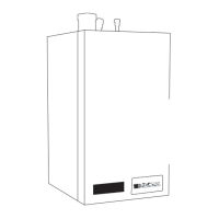
14
15
16
L L
230 VAC
Power supply
ST-6
Fuse
To Ground
OFFOFF
Service Switch
ON
Junction Box
Junction Box
INNOVATIVE CONDENSING TECHNOLOGY
By Hamilton Engineering, Inc.
(FIGURE 1-4) HOW TO REMOVE THE FRONT COVER
Page 7 of 50