34000 Autry Street, Livonia, MI 48150 • 800.968.5530 • Fax 734.419.0209 • www.hamiltonengineering.com • LIT91127 REV 3/09
MAINTENANCE
PART 8. MAINTENANCE
A. MAINTENANCE PROCEDURES
Once a year, a qualied service technician should perform maintenance on your EVO equipment to
ensure that everything is operating safely and efciently. The owner can make necessary arrangements with a
qualied heating contractor for proper maintenance of the heater. The equipment installer must also inform the
owner that the lack of proper care and maintenance of the heater may result in a hazardous condition. The
installer should discuss the contents of the User’s Information Manual with the owner.
B. ANNUAL INSPECTION
An inspection should cover at least the following areas.
Caution : Before removing the door of the appliance, switch off the electrical power supply to it.
a. Remove the front cover and check all pipes, lines and connections, heat exchanger (top, bottom)
for traces of water and water leakage.
b. Inspect the top of the casing and/or the top of the appliance for water leakage or traces of water
from the air supply pipe or the air vent.
c. Open the condensate drain cleanout and remove any dirt. Flush so there is absolutely no
restriction in water ow, and replace. (see cleaning instructions below in section C).
d. If the inspection is being carried out by a Hamilton Engineering Certied Technician, connect your
computer and check the service page for error messages, starts and failed/successful starting efforts.
e. Dismantle the burner unit: remove the (6) 6mm nuts and the ignition cable, and move the burner
unit forward. Remove the plug of the fan cable to the fan once the burner has been pulled halfway
from the appliance. Check the inside of the heat exchanger: only clean residue at the bottom
side of the heat exchanger coil. Use a vacuum cleaner, and do not push the residue between the
openings of the coils if at all possible as this may impede the ow of the products of combustion.
It is possible to use clear water to rinse any remaining residue away – the water will automatically
ow to the condensate drain point. (See cleaning instructions below in section D).
f. Dismantle the air gas mixing plate or chamber on the suction side of the fan; check the blade wheel
of the fan, and clean if required.
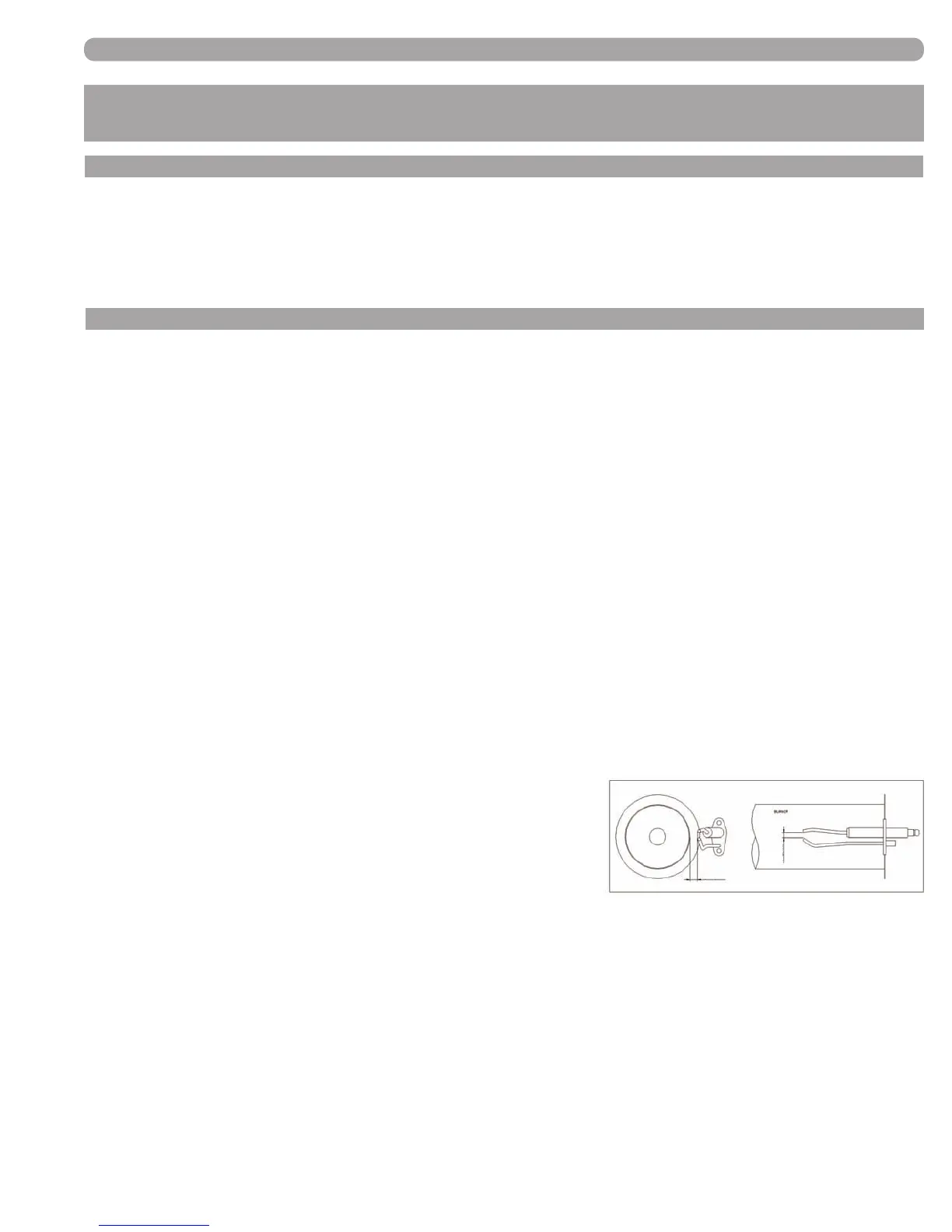
g. Check the distance from the electrode to the burner;
there Should be a 3/8” gap in between the two. If the
existing electrode pins must be adjusted, caution
must be exercised as they will likely be brittle from
exposure to the ame; try to bend them as close to
the burner door insulation as possible. New electrodes
will be less susceptible to breakage during adjustment.
The following steps require the power supply be turned back
on; extreme caution must be exercised when performing
3/8”
3/16”
service with the power supply on and the door off.
h. Fire the appliance on maximum output, and measure and adjust the CO2 percentage as required.
i. Fire the appliance on minimum output, and measure and adjust the CO2 percentage as required.
See Table 3-3, Page 12 for specic settings.
j. Listen for any unusual noise in the circulating pump and the fan.
All ndings and concerns should be discussed with the appliance owner after the inspection is complete.
(FIGURE 8-1) DISTANCE
FROM ELECTRODE
TO BURNER
Page 33 of 50