34000 Autry Street, Livonia, MI 48150 • 800.968.5530 • Fax 734.419.0209 • www.hamiltonengineering.com • LIT91127 REV 3/09
Optional Connection
Must connect + to + and - to - between appliances in cascade
Thermostat
Remote
-+
Cascade
Connection
Sensor
10k
Thermistor
External
Temperature
Optional Connection
Used for storage tank or common line sensing
Optional Connection
Normally open dry contact or Open Term Thermostat
Optional Connection
Building management system
Optional Connection
For use with Central heating for outdoor reset
653 421
To Pump
Fused switch or from
a maximum 15 amp
dedicated circuit
breaker
208 - 240 VAC
L
LL
60 Hz
208 - 240 VAC
L
Pump
Power Supply
To Ground
15 16 17 201918
-+
0-10 VDC
Sensor
10k
Thermistor
Outside
Temperature
7 8 109
Lock Out
Signal
Dry Contact
Additional
Heat Source
Dry Contact
11 12 1413
Optional Connection
Optional Connection
For use with additional heat needed w/cascade
For use with alarm bell / light
Junction Box
A B C D E F G H
I
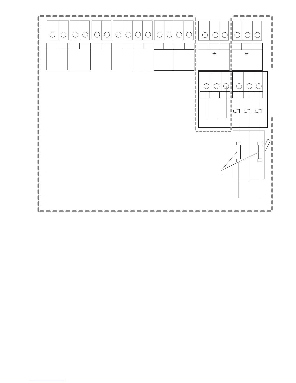
(FIGURE 2-1) FIELD WIRING CONNECTIONS
Page 9 of 50
A. External sensor connection - system temperature sensor, senses water temp in a storage tank or a
heating loop.
B. Cascade Connection - communication cables get connected here and “daisy chained” to all heaters/
boilers in a cascade. This is polarity sensitive.
C. Remote Thermostat - normally jumped. A room thermostat may be connected here to enable/
disable the heater/boiler.
D. 0-10 VDC - connect a 0-10 VDC output here to vary set point temperature.
E. Outdoor Sensor - outdoor air sensor, set point will adjust based on outdoor air temperature (not
needed if 0-10 VDC output is connected).
F. Lock Out Signal - alarm bell or light may be connected here.
G. Additional Heat Source - dry contacts that will close a thermostat on an extra heater/boiler if the
cascade system is at 100% of capacity.
H. Pump - the pump leads that are in the electrical box originate here.
I. Power Supply - main power connections in the electrical box originate here.