Note: It is recommended that the anti-bounce device is fitted
only when needed (e.g. when cutting thin sheet material or
thin walled metal tube etc). At other times store away off the
machine for future use.
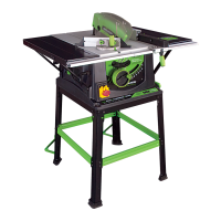
The pillar of the anti-bounce device fits into the socket
in the mitre gauge base, and is held in place by a set screw.
See Fig 15. To attach or remove the pillar the mitre gauge
faceplate will have to be removed to gain access
to the set screw.
8. TOP BLADE GUARD
The top blade guard must be fitted to the machines riving knife.
The ‘split’ line along the top of the guard indicates the cutting
line of the saw blade below. Graphics on the guard further
reinforce the cutting line of the saw blade.
WARNING: The machine must be disconnected from
the mains supply when installing the blade guard.
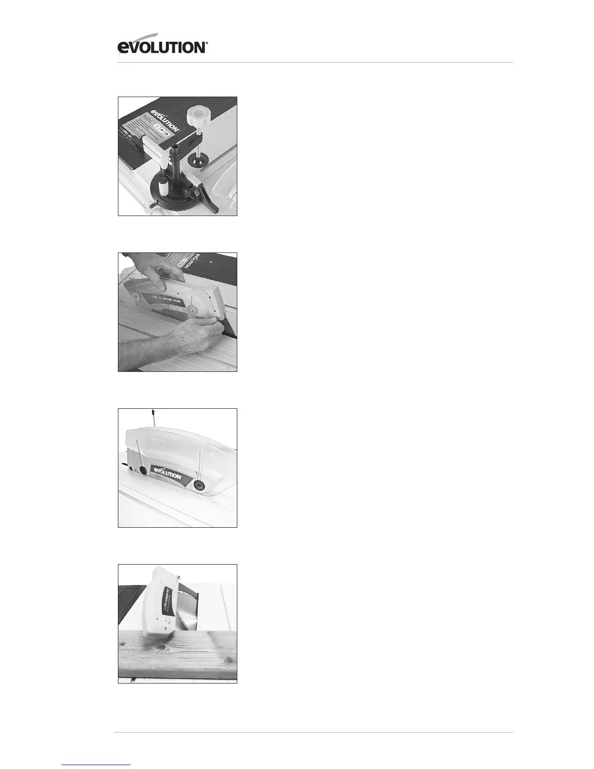
1. Raise the blade to its full height to fully reveal the riving knife.
2. The guards locating pin should be positioned through the
hole in the riving knife and the washer and wing nut fitted to
one side. The blade guard must move up and down easily and
smoothly, so do not over-tighten this wing nut. See Fig 16.
3. Check the operation of the blade guard. Ensure that it is
working efficiently and covers the blade entirely at the sides as
well as the crown.
4. Lower the blade a little and recheck that the blade guard
operation.
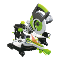
5. When satisfied that the blade guard works throughout the
blades height adjustment range, check that when the blade is
fully lowered, the blade guard and side covers are in contact
with the table top. See Fig 17A.
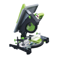
Note: Guard Setting for Bevel, Mitre & Compound Cuts
When bevel, mitre or compound cutting it may be necessary
to remove the left or both blade side covers. See Fig 17B.
Use a crosshead screwdriver to remove the side cover
attachment screws and their plate washers. Securely store
the side covers, screws and washers for future use.
Fig 15
Fig 16
Fig 17A
Fig 17B