1. Locate the Rip Fence in the Fence
Rail to the RH side of the Blade.
2. Raise the saw blade (see Operation Controls 2)
3. Slide the Rip Fence along the Fence Rail
until it rests against the raised saw blade.
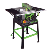
4. Look through the Rip Fence magnifier, and gently move the
Fence Rail to the right or left until the ‘0’ position on the scale
coincides with the datum line in the magnifier. See Fig 12.
5. Check, and when satisfied that calibration has been
achieved, tighten the six Fence Rail nuts securely.
6. Lower the Blade.
Note: The Rip Fence simply slots into the Fence Rail, and can
be locked into position anywhere along the rails length, and at
either side of the machine by pressing the locking lever down.
6. CHECKING/ADJUSTING THE RIP FENCE
When the Fence Rail and Rip Fence have been attached
to the machine, the Rip Fence should be checked to
ensure that it lies parallel to the blade.
1. Raise the blade to its full height.
2. Rest a straight-edge or similar against the blade.
3. Bring the Rip Fence up to the
straight-edge and check for parallelism.
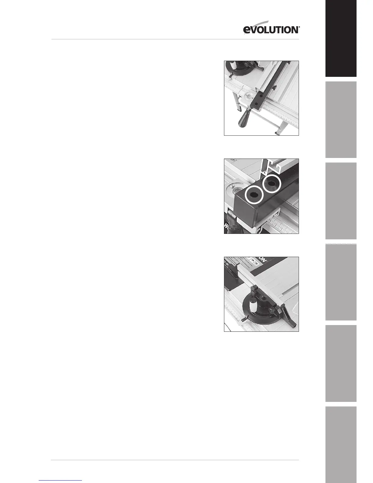
4. If adjustment is needed, gain access to the two socket headed
screws through the two holes in the steel carrier. See Fig 13.
5. Loosen these screws using the correct sized
allen key, and adjust the fence as required.
6. Tighten and re-check the Rip Fence when
correct alignment has been achieved.
7. Lower the blade.
7. SLIDING MITRE GAUGE
Note: The sliding mitre gauge fits in either
of the inverted ‘T’ slots in the machine table.
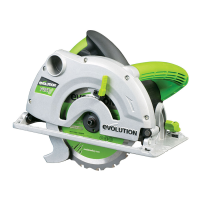
The adjustable aluminium faceplate is held in the plastic
protractor base of the mitre gauge by two ø6mm domed
headed screws and thumb nuts. The anti-bounce device can be
fitted into the socket incorporated into the mitre gauge base.
See Fig 14. Turning the locking handle anti-clockwise allows
the mitre gauge angle to be adjusted. Use the protractor scale
and pointer and set the gauge to the desired angle. Tighten the
vertical handle when the required angle has been set.
Fig 12
Fig 13
Fig 14