4. Installation V10k automatic
12
EN
4.3 Mounting
(See mounting drawing chapter 7.2.)
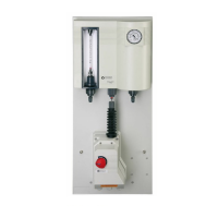
4.3.1 Gas Control Unit
1 Mount the gas control unit to a vertical
surface, wall, etc. with the dowels and
screws supplied loose. The flowmeter
should be at a height suitable for reading.
Make shure that the mounting plate is
exactly level and not distorted when tigh-
tening the nuts. The mounting plate
should not touch the wall.
4.3.2 Injector
When installed with rigid pipes the injectors
need not to be fixed elsewhere. When connec-
ted to flexible tubes the injectors have to be
fixed as shown in chapter 7.2.
Nozzle (with stamped number) and tailway
(with stamped letter) are supplied loose.
1 Place the o-rings on both and apply some
vacuum grease (do not use mineral
grease).
2 When assembling nozzle and tailway into
the injector body pay attention to the
flow direction (see arrows on the injector
body). Turn only by hand up to the stop.
For measuring the injector vacuum a 1/4" con-
nection is provided.
Operation range:
Up to 4 kg/h:
standard injector W3T171369 (3/4") or anti-
syphon injector W3T171370
Above 4 kg/h:
standard injector W3T171367 (1") or anti-
syphon injector W3T171368
The anti-syphon injectors are necessary, when
depression can occur in the water pipe, e.g. by
water flowing downwards.
Injector W3T171369/W3T171370
Connection at the throat:
3/4“ hose or threaded tube
If connected to 3/4" rigid tube, the part of the
nozzle that is prepared for accepting flexible
tube can be removed. Carefully deburr and
remove the residues.
The gas connection can be turned in 45° steps
after loosening the union nut. Lock before
tightening the union nut. Tighten only by
hand!
Injector W3T171367/W3T171368
Connection at the throat:
PVC tube DN 25 (Ø32 mm)
Connection at the tailway:
PVC tube with 3/4“ inner thread
The gas connection can be turned in 60° steps.
To do so remove the 6 bolts, remove the upper
part of the housing and fix again in the desired
position. Tighten the bolts equally.
4.3.3 Point‐of‐application
If the point-of-application is a pressurized
main or is higher than the injector, the solu-
tion line should incorporate a check valve and
terminate in a solution injection tube assem-
bly.
WARNING
Danger due to chlorine gas (gas escape)!
To avoid the risk of injuries due to chlorine
gas, the system must be installed in such a
way that gas is only able to escape into the
room where the gas tanks are stored or into
a separate plant room in the event of a gas
leak. All parts of the system that are liable to
be pressurized (e.g. chlorine tanks, vacuum
control valves, safety pressure relief valves
with activated carbon filters) must therefore
be installed in these rooms. The parts of the
system that are under vacuum may be
installed in another room that is not subject
to specific regulations.
WARNING
To avoid possible severe personal injury or
damage to the plant this equipment should
be installed, operated and serviced only by
trained qualified personnel. Do not modify
the installation beyond what is described in
this manual without explicit consent of Evo-
qua.
ATTENTION
Never shorten the tailway. The tube connec-
ted to the tailway must be straight for at
least 0,30 m more. Otherways the flow in
the pressure-recovery zone will be interrup-
ted and prevent normal performance.