3. Description V10k automatic
8
EN
3. Description
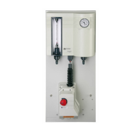
3.1 Principle of operation
Operating water passes through an injector
(14) and creates a vacuum. This vacuum makes
the vacuum control valve (4) on the chlorine
tank (1) open. Chlorine gas enters the control
unit (8) under the influence of the vacuum and
passes through the flowmeter and further to
the injector. There it mixes with the operating
water which then passes to the solution distri-
bution system.
If the operating water is shut off, the vacuum
breakes down and the vacuum control valve
interrupts the chlorine flow. In case of a leak in
the tubing from the vacuum control valve to
the injector or in the chlorinator, only air can
enter into the system, but no chlorine can
escape. If the vacuum control valve leakes and
pressurized chlorine flows into the vacuum
lines, a relief valve (6) blows the chlorine into
the vent line and into an activated carbon filter
(5).
It is highly recommended to have the sensor of
a gas monitoring system installed in the chlo-
rine room.
3.2 Control possibilities
The gas flow is directly indicated on the flow
meter in g/h or kg/h. Within the dosing range,
limited by the v-notch, every dosage rate can
be adjusted (max. 15 kg/h).
automatic:
Dosage rate is adjusted by the positioner. The
positioner is controlled depending on water
flow and/or chlorine residue.
semi‐automatic:
• Dosage rate is adjusted manually. The
injector is switched on and off by sole-
noid valves in the water supply line or by
booster pump.
• Dosage rate is adjusted by the positioner
switched up and down via an external
controller. The injector is switched on and
off by solenoid valves in the water supply
line or by booster pump.
manual:
Pull out the knob on the positioner and turn to
adjust the dosing rate (e.g. in case of failure on
the automatic control). To turn back to auto-
matic control push back the knob and slightly
turn it until it snaps in.