V10k automatic 4. Installation
13
EN
The injection tube consists of a pvc stop valve
and a tube with threaded connection, that
extends to approx. 1/3 of the mains diameter
when extended.
It is recommended that all solution delivery
lines be fitted with a suitable valve and drain
pipe to enable any pressure build up to be
safely released prior to maintenance work.
4.3.4 Water supply
To operate the injector, a water supply pipe of
at least 3/4“ diameter is necessary according
to the operating conditions.
There must always be sufficient operating
water available at an adequate supply pres-
sure (see Technical Data for details). The ope-
rating water must not contain any particulates
(potable water quality).
Water pressure and quantity depend on the
maximum dosing capacity, the counterpres-
sure at the point of application, the difference
in geodetic altitude between chlorinator and
point of application and the friction in the
dosage line. On these values depend the selec-
tion of the injector.
If the operating water pressure is too low, a
booster pump is required.
The water line should include a suitable shut-
off valve, strainer, pressure gauge, pressure
reducing valve check-valve and solenoid valve
(see chapter 7.1).
It is recommended that all solution delivery
lines lines be fitted with a suitable valve and
drain pipe to enable any pressure build up to
be safely released prior to maintenance work.
4.4 Gas supply line
For reducing the pressure from the chlorine
tanks, a vacuum control valve and a safety
relief valve are necessary (see also typical ins-
tallation).
For the vacuum control valves a separate inst-
ruction manual „Gas supply“ is available.
4.4.1 Gas suction line
The diameter of the suction line between
vacuum control valve, control unit and injector
depends on the the gas flow and the distance
(see table below).
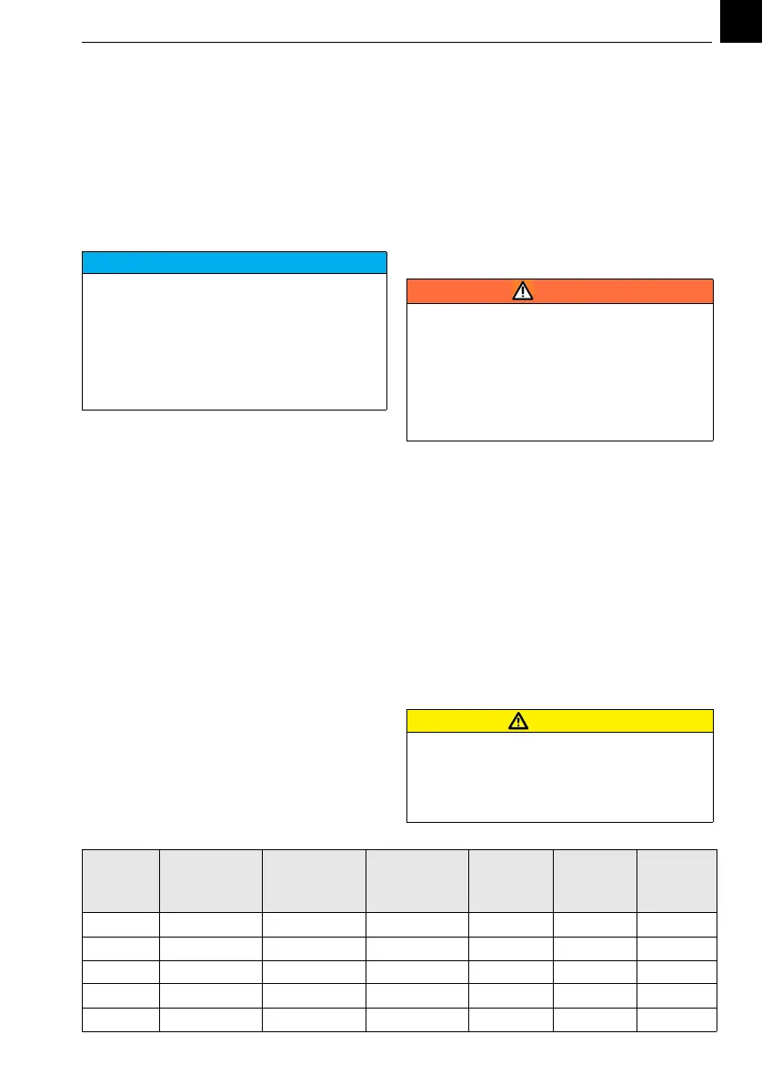
Max. tube/pipe length from vacuum control valve to the V10k
NOTICE
Behind the point-of-application a pipe
length of at least 10...15 x pipe diameter is
necessary for a homogenious mixing of the
solution into the main water. After that,
samples can be taken for residue control
etc. If the point-of-application is into a basin,
channel etc. a diffusor can be supplied (refer
to the project documentation.
WARNING
Danger due to chlorine gas !
The gas control unit must be connected to a
vacuum gas supply only.
Do not open the cylinder or drum valve until
the system has been fully installed and the
pre-start checks are being carried out.
Refer to the safety information of the gas
supplier and the safety data sheet!
ATTENTION
When using polyethylene pipes don't install
them in narrow, badly vented protection
pipes or in the ground to prevent the pipe
from fast embrittling under the influence of
chlorine.
Feed of
Cl2, SO2
in g/h
PE hose
6,35 mm
(1/4“)
PE hose
9,5 mm
(3/8“)
PE hose
12 mm
(1/2“)
PVC pipe
DN 15
PVC pipe
DN 20
PVC pipe
DN 25
200 250 m 1200 m 3000 m - - -
400 146 m 670 m 1510 m 3600 m - -
1000 24 m 88 m 852 m 1710 m - -
2000 6 m 33 m 107 m 320 m 1094 m -
3000 3 m 16 m 53 m 179 m 607 m 1853 m