7. Drawings V10k automatic
42
EN
7. Drawings
7.1 Typical installations
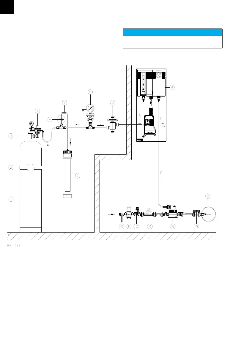
7.1.1 Basic chlorinator installation
1 Chlorine cylinder
2 Holding bracket
3 Cylinder main valve
4 Vacuum control valve
5 Activated carbon filter
6 Safety relief valve
7Vent line
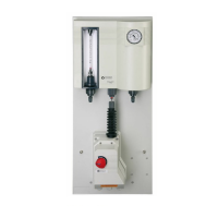
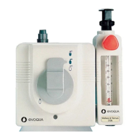
8 Gas control unit V10k
9 Main line being treated
10 -13 Operating water supply
14 Injector
15 Point of application
16 Vacuum safety valve
17 Contact vacuum pressure gauge
NOTICE
The gas monitoring system is not always
displayed in the following drawings.