4. Installation V10k automatic
18
EN
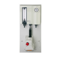
4.8.2 Check for gas leaks
1 Keep the valves on the chlorine cylinder
or drum closed.
2 Open the valves in the water supply line
to the injector and at the point of applica-
tion. A vacuum of min. 200 mbar must be
indicated on the manometer of the cont-
rol unit.
3 Check that the flowmeter float remains at
his bottom stop. Any movement of the
float indicates an ingress of air on one of
the following locations:
• through the safety relief valve
• through the o-ring on the bottom of
the flowmeter or
• through cracks in the flowmeter
• through the o-rings at the pipe con-
nections
• through any incorrectly cemented
joints or slack unions in the pipework.
Repair any leaks immediately.
4 Open the valves on the chlorine cylinder
or drum carefully and close again.
5 Check for leaks. Hold a bottle of 25%
ammonia solution in the vicinity of the
part under test. In case of a leak the esca-
ping gas will form dense white clouds.
6 In case of a leak check that the cylinder or
drum valve is closed. Open the auxiliary
valve(s). Let the operating water flow.
Open the regulating knob of the positio-
ner and let the gas from the gas lines be
sucked away until the float in the flowme-
ter of the V10k is down on the lower stop.
Immediately tighten the leak.
7 When all parts have been checked:
Open the valve on the chlorine cylinder or
drum again.
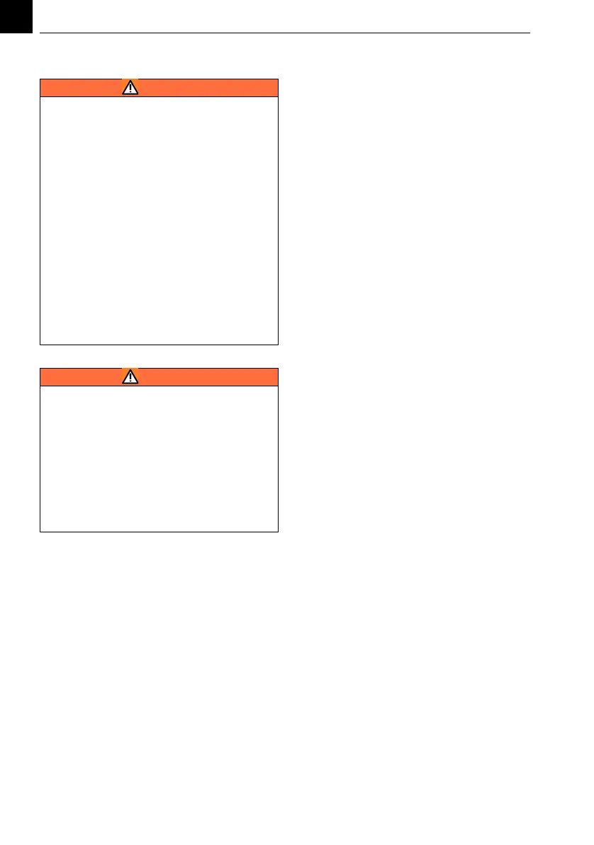
8 Adjust the desired dosing capacity. The
operation vacuum is shown on the pres-
sure gauge of the V10k.
9 Close the valves on the chlorine cylinder
or drum. Within a minute the float in the
flowmeter of the V10k should be down on
the lower stop. Otherwise refer to step 2.
4.9 Commissioning
4.9.1 General
When the water and gas leak test have been
performed successfully, the system can be
started as follows (the positions refer to the
drawing in chapter 3.3)
1 Activate the gas warning device.
2 Open the point-of-application
3 Open the operating water valve incl sole-
noid valve.
4 If necessary start the booster pump.
5 Adjust the injector water pressure at the
reducing valve
6 Open the gas cylinder valve (3) one turn.
7 Open the vacuum control valve (4).
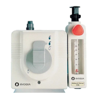
8 Adjust the dosage manually, read the
dosing rate at the flowmeter of the V10k.
9 Switch the positioner to automatic opera-
tion (knob pushed in), set the control to
the suitable dosage rate.
10 Check that the dosage rate on the control
corresponds with the display on the flow-
meter. For further information see the
instruction manual of the control.
WARNING
Danger due to chlorine gas !
Chlorine gas irritates the respiratory tracts.
Contact with chlorine gas in high concentra-
tions irritates and damages the membranes,
respiratory system and the skin. In extreme
cases death can result due to suffocation.
When inspecting the system for leakage
always keep your gas mask to hand.Practice
use of the mask regularly.
If chlorine gas is discharged, only use a gas
mask which is independent of ambient air!
Do not tolerate any leakages in the chlorine
system.
Before servicing the system the gas supply
must be closed off directly on the gas cylin-
ders or tank and the chlorine gas in the sys-
tem must be consumed completely. In case
of strong chlorine smell put on your gas
mask.
WARNING
Danger due to chemicals !
Testing for chlorine or SO2 gas leaks is
accomplished by introducing ammonia
fumes to the area under test. Any escaping
gas will combine with the ammonia to form
dense white clouds. Liquid ammonia solu-
tion must not be applied directly to the part
being tested. Hold a bottle of 25% ammonia
solution in the vicinity of the part under test.
Ammonia must not be inhaled, splashed or
spilled.