Do you have a question about the Evoqua V10K and is the answer not in the manual?
Explains manual structure, target audience, and conventions used.
Defines symbols and notations used for warnings, notes, and instructions.
Specifies the correct application of the V10k system and prohibited uses.
Outlines fundamental safety rules for operating and maintaining the system.
Details safety precautions unique to the V10k system and chlorine/SO2 handling.
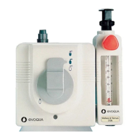
Describes the functional mechanism of the V10k vacuum gas feeder.
Explains the methods for controlling gas dosage: automatic, semi-automatic, manual.
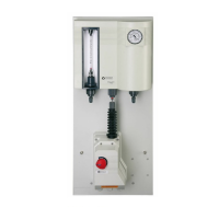
Illustrates the physical layout and components of a basic chlorinator installation.
Provides performance specifications, operating ranges, and physical dimensions.
Lists all parts and accessories included with the V10k system.
Guidelines for handling, moving, and storing the equipment to prevent damage.
Specifies ideal site conditions, temperature, and access for installation.
Provides instructions and diagrams for physically installing the gas control unit and injectors.
Details the requirements for the operating water connection to the injector.
Covers the selection and installation of piping for the gas suction system.
Instructions for wiring the system's electrical components safely and correctly.
Guides for setting the positioner's operational limits and feedback.
Step-by-step instructions for correctly installing the flowmeter tube.
Procedure for accessing internal components by removing the unit's cover.
Pre-operation checks, focusing on water leak tests and system readiness.
Method for detecting leaks in the gas system using ammonia detection.
Steps required to start up and activate the system after installation and checks.
Emphasizes the necessity of proper training for personnel operating the system.
Overview of routine operational tasks and checks.
Procedure for initiating the gas feed and dosing process.
Instructions for safely halting the gas feed and dosing.
Detailed steps for replacing empty chlorine or SO2 gas cylinders.
Procedure for safely shutting down the system for storage or repairs.
Troubleshooting guide for identifying and resolving common system issues.
Schedule of recommended maintenance tasks and inspection frequencies.
Procedure for replacing the carbon media in the filter unit.
General guidelines to ensure system longevity and safe operation.
Instructions for cleaning various components using appropriate methods.
Routine maintenance procedures for the main chlorinator unit.
Covers service procedures for different types of injectors.
Lists available kits containing parts for scheduled maintenance replacements.
Maintenance procedures and checks for the positioner unit.
Diagrams illustrating common system configurations and setups.
Detailed diagrams showing dimensions and mounting points for components.
Diagrams for installing the standard 3/4" injector.
Diagrams for installing the anti-syphon 3/4" injector.
Diagrams for installing the 1" injectors.
Diagrams showing the 3/4" injector with associated accessories.
Diagrams for the 3/4" anti-syphon injector with accessories.
Diagrams showing the 1" injector with associated accessories.
Detailed diagram of the V10k chlorinator with numbered parts.
Side view illustration of the V10k unit highlighting key components.
Close-up diagram of the differential regulating valve assembly.
Table listing flowmeter models and their corresponding operational ranges.
Table detailing V-notch control ranges and available spare parts.
Overview diagrams and part listings for different injector types.
Diagram and part list for the 1" anti-syphon injector.
Diagram and part list for the 3/4" standard injector.
Diagram and part list for the 3/4" anti-syphon injector.
| Brand | Evoqua |
|---|---|
| Model | V10K |
| Category | Industrial Equipment |
| Language | English |