V10k automatic 6. Maintenance
41
EN
6.6.3 Replacing the board
1 Disconnect the positioner from the mains.
2 Remove the knob and the cover.
3 Remove all connectors from the board
4 Remove cam wheel (6) (Allan key 1,5 mm)
5 Remove all 4 screws (5)
6 Remove the board with transparent cover
7 Remove the toothed wheel from the
potentiometer shaft
8 Place the transparent cover onto the new
board
9 Place the toothed wheel onto the poten-
tiometer shaft, push to the stop and fix.
10 Fix the new board with the wheels mat-
ching
11 Place the cam wheel.
12 Place the connectors, adjust the limit
switches and the potentiometer, close the
cover.
13 Check for function.
6.6.4 Replacing the motor‐gear‐as‐
sembly
1 Disconnect the positioner from the mains.
2 Remove the knob and the cover.
3 Remove all connectors from the board
and the ground
4 Remove screws (3)
5 Take out the motor-gear-assembly.
6 Remove the board and place onto the
new motor-gear-assembly.
7 Mount motor-gear-assembly with the
toothed wheel matching with the rack.
8 Place the connectors, adjust the limit
switches and the potentiometer, close the
cover.
9 Check for function.
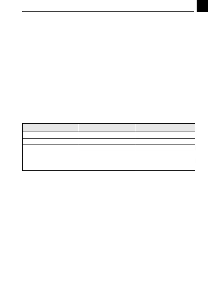
6.6.5 Spare parts for the positioner
The part numbers are valid for positioners supplied in or after December 2016. For all positioners
supplied before please give the serial number of the positioner when ordering spare parts.
Part no.
Bellow W3T172913
Rack incl. grease W3T159883
Board 230 V W3T343350
115 V W3T343531
Motor-gear assembly 230 V W3T353676
115 V W3T353677