TTL Inputs (GP In 5, 6, 7, 8)
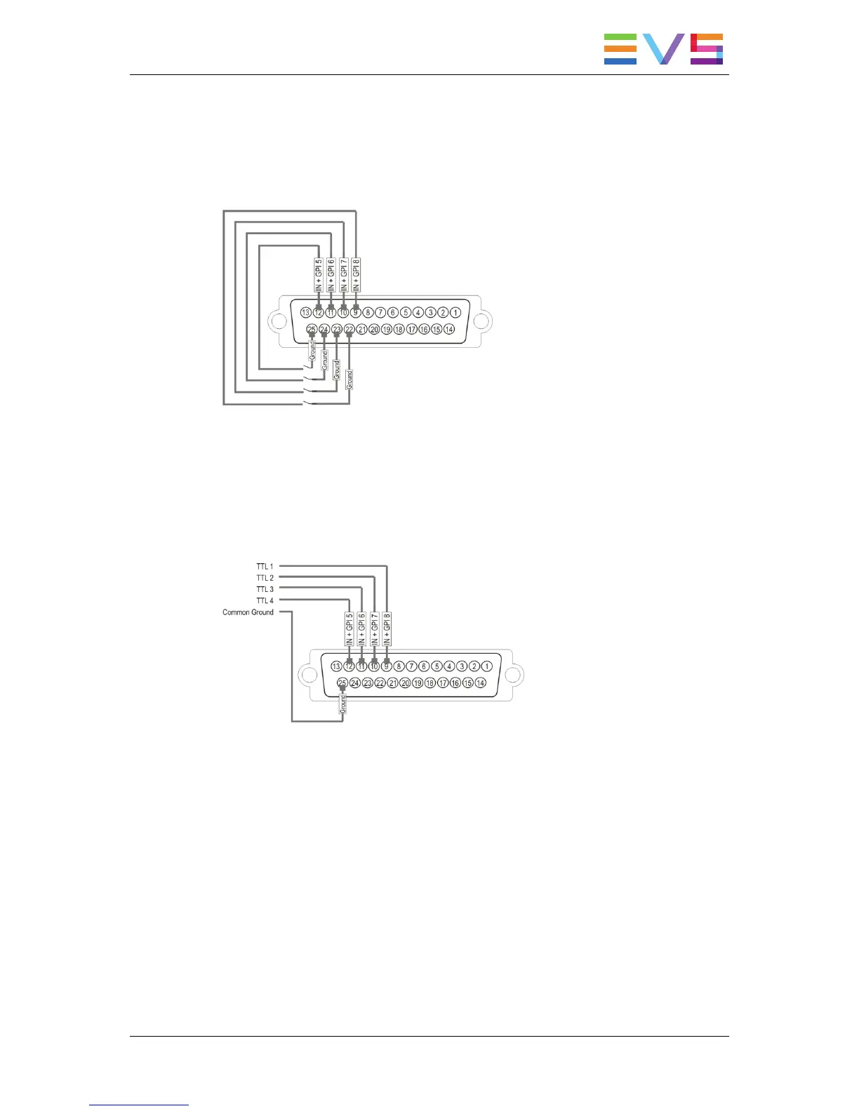
Relay Inputs Pin-Out
The relay must be connected between the ground and the corresponding TTL input on the
DB-25.
TTL Inputs Pin-Out
Each TTL input on the DB-25 is directly connected to the pin of the TTL connector on the
device triggering the GPI. The ground must be common between the DB-25 connector of
the XT3 serverand the external device.
Specifications
• each pin can be individually configured as an output or an input
• internal 4K7 pull up to +5V
• low level Vi<1.5 Volt (U12=74HC245)
• high level Vi>3.5 Volt (U12=74HC245)
• optional TTL compatible level (U12=74HCT245)
HARDWARE TECHNICAL REFERENCE MANUAL XT3 Server 12.05
5. Hardware Installation and Cabling 81


![Preview: EVS XT[2]](https://data.easymanua.ls/products/617905/200x200/evs-xt-2.webp)


