Design and function
Transport and installation
099-007010-EW501
07.09.2016
4.1.7 Shielding and plasma gas supply
Risk of injury due to improper handling of shielding gas cylinders!
Improper handling and insufficient securing of shielding gas cylinders
can cause serious injuries!
• Place shielding gas cylinder into the designated holder and secure with
fastening elements (chain/belt)!
• Attach the fastening elements within the upper half of the shielding gas
cylinder!
• The fastening elements must tightly enclose the shielding gas cylinder!
An unhindered shielding gas supply from the shielding gas cylinder to the welding torch is a
fundamental requirement for optimum welding results. In addition, a blocked shielding gas
supply may result in the welding torch being destroyed.
• Always re-fit the yellow protective cap when not using the shielding gas connection.
• All shielding gas connections must be gas tight.
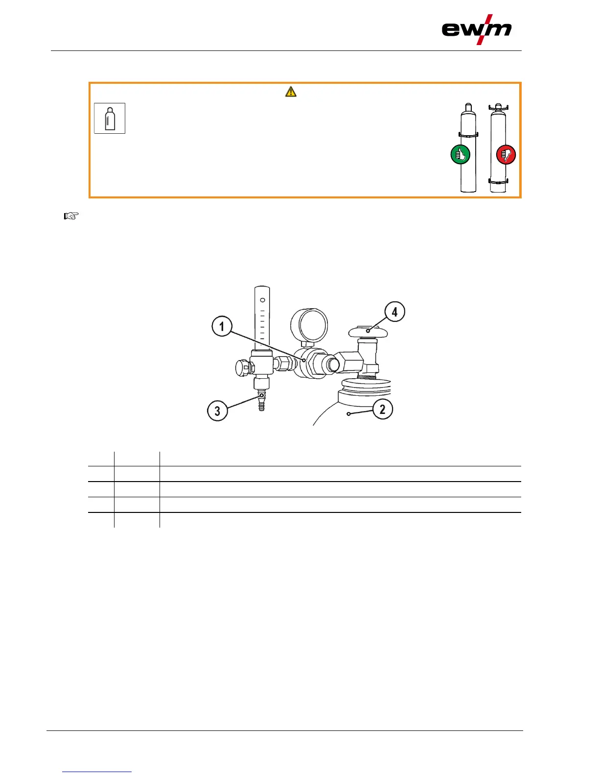
4.1.7.1 Pressure regulator connection
Figure 4-7
Output side of the pressure regulator
• Before connecting the pressure regulator to the gas cylinder, open the cylinder valve briefly to blow
out any dirt.
• Tighten the pressure regulator screw connection on the gas bottle valve to be gas-tight.
• Screw gas hose connection crown nut onto the output side of the pressure regulator.