Design and function
Transport and installation
099-007010-EW501
07.09.2016
4.1.9 Function sequences/operating modes
4.1.9.1 Currentless Test - Simulation mode
Prior to beginning welding, the user can simulate the selected current and time parameters without
actually welding. The toggle switch for no-power test is used for this. The selected current and time
parameters can now be simulated as for the normal welding process.
4.1.9.2 Explanation of signs and functions
Main current (minimum to maximum current)
Secondary current (0 % to 100 % of AMP)
Gas pre-flows (shielding gas)
Gas post-flows (shielding gas)
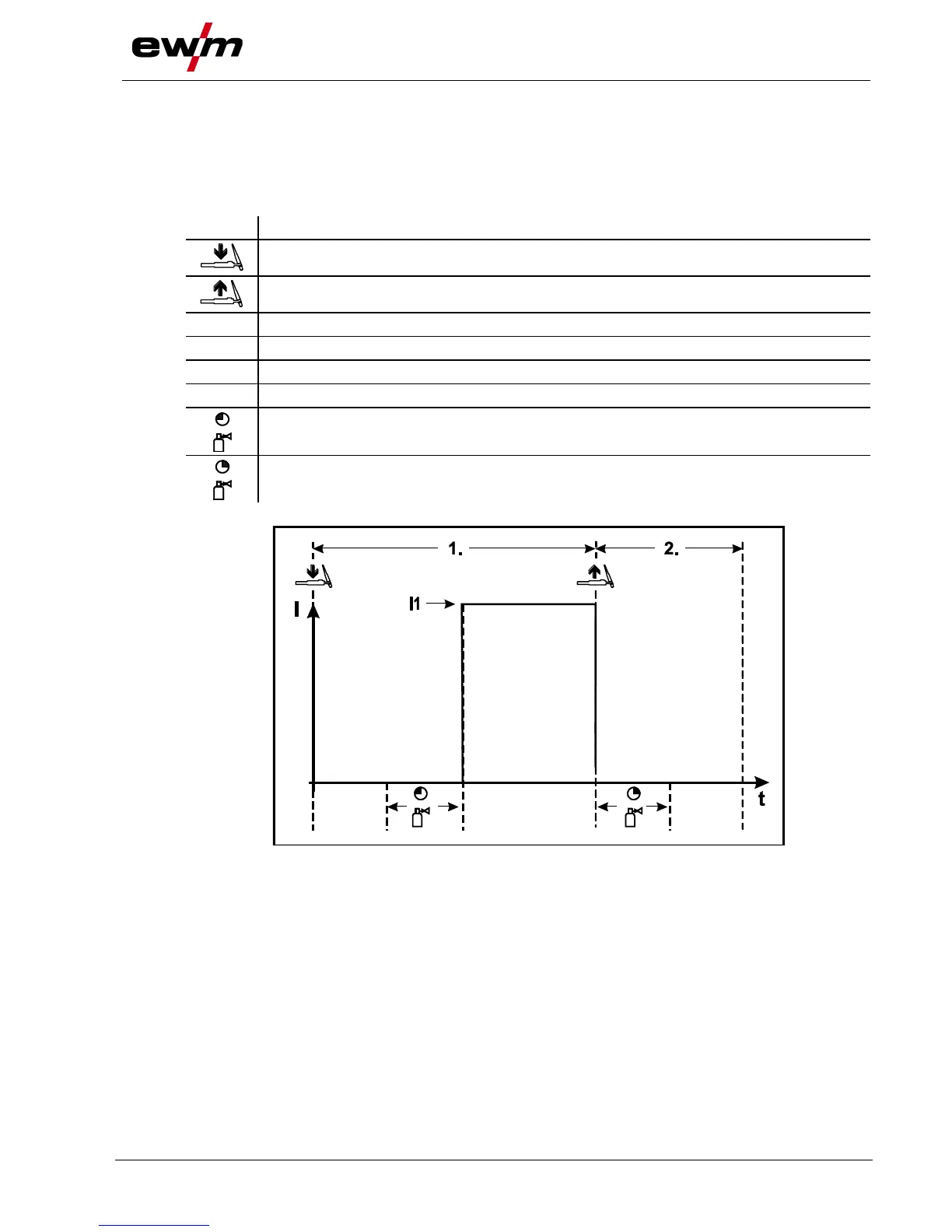
4.1.9.3 Non-latched operation without Up- und Downslope
Figure 4-12
1st cycle:
• Activate torch trigger 1 or the foot-operated remote control.
• The gas pre-flow time elapses.
• The arc ignites.
• Welding current I1 flows.
2nd cycle:
• Release torch trigger 1 or the foot-operated remote control.
• Arc is extinguished.
• The set gas post-flow time elapses.