Design and function
Transport and installation
099-007010-EW501
07.09.2016
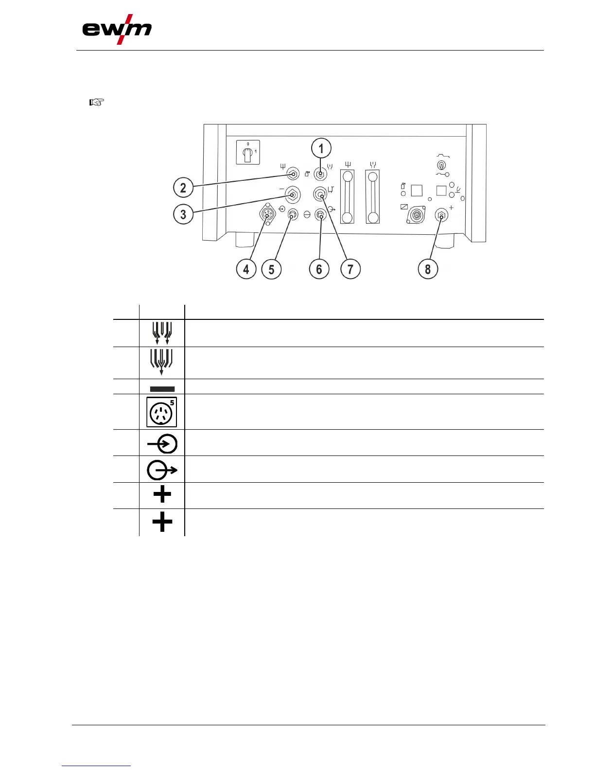
4.1.8 Welding torch and workpiece line connection
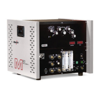
4.1.8.1 microplasma 20, 50
Before commissioning, the plasma welding torch must be equipped for the welding JOB and
correspondingly set/adjusted!
Shielding gas connecting nipple (G1/4” left)
Connection to the welding torch or gas metering unit
Plasma gas connecting nipple (G1/4” right)
Connection to the welding torch or gas metering unit
Welding current connection socket, welding torch
5-pole connection socket, welding torch control lead
Coolant return from welding torch
Coolant supply to the welding torch
Pilot current connection socket
Plasma welding torch nozzle potential
Connection socket, “+” welding current
Connection for workpiece lead
• Insert the plug on the welding current lead into the "-" welding current connection socket and lock.
• Insert the plug of the pilot power line into the "+" pilot current connection socket.
• Insert the torch control lead plug into the “5-pole connection socket, welding torch control lead” and
lock.
• Screw the connection coupling of the plasma gas line onto the G1/4" connecting nipple, plasma gas
connection.
• Screw the connection coupling of the shielding gas line onto the G1/4" connecting nipple, shielding
gas connection.
• Engage the coolant hose connecting nipples in the corresponding quick connect couplings.
Red return in red coupling (coolant return) and blue feed in blue coupling (coolant feed).
• Insert the cable plug on the work piece lead into the "+" welding current connection socket and lock by
turning to the right.