Design and function
Transport and installation
099-007010-EW501
07.09.2016
Before commissioning, the plasma welding torch must be equipped for the welding JOB and
correspondingly set/adjusted!
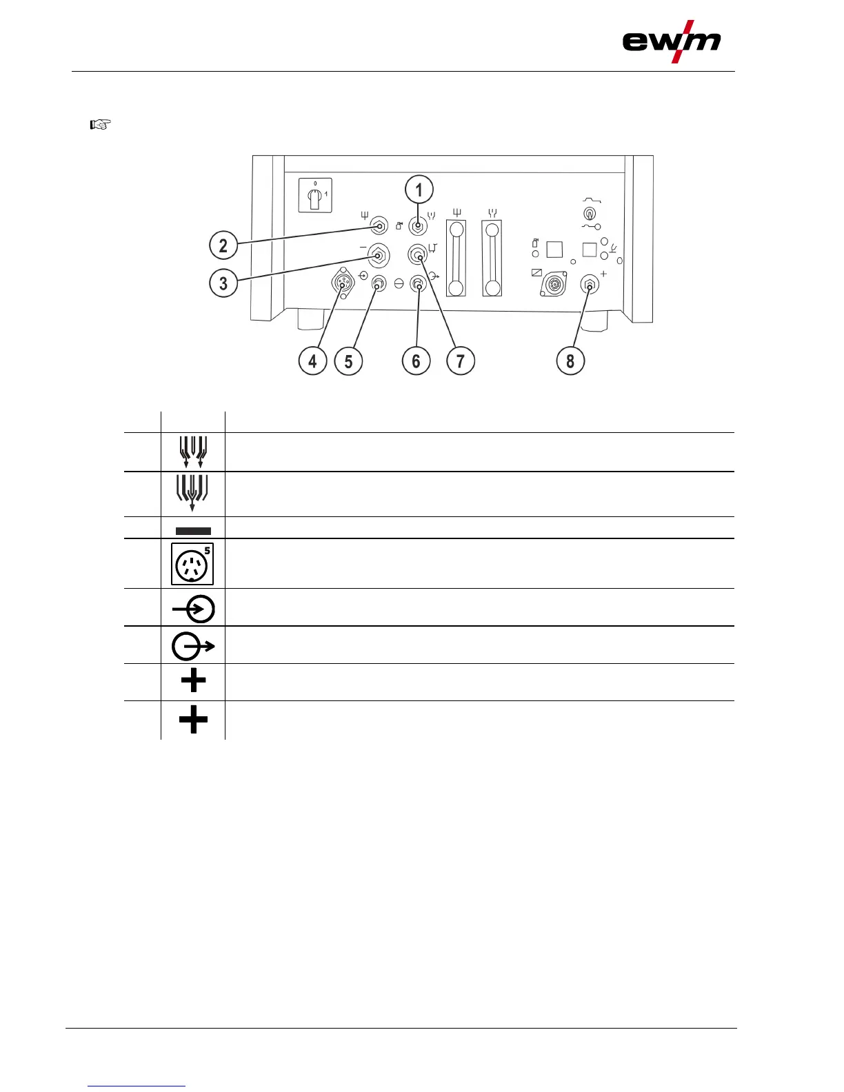
Shielding gas connection (coupling type 20)
Connection to the welding torch or gas metering unit
Plasma gas connection (plug nipple type 20)
Connection to the welding torch or gas metering unit
Welding current connection socket, welding torch
5-pole connection socket, welding torch control lead
Coolant return from welding torch
Coolant supply to the welding torch
Pilot current connection socket
Plasma welding torch nozzle potential
Connection socket, “+” welding current
Connection for workpiece lead
• Insert the plug on the welding current lead into the "-" welding current connection socket and lock.
• Insert the plug of the pilot power line into the "+" pilot current connection socket.
• Insert the torch control lead plug into the “5-pole connection socket, welding torch control lead” and
lock.
• Screw the connection coupling of the plasma gas line onto the G1/4" connecting nipple, plasma gas
connection.
• Screw the connection coupling of the shielding gas line onto the G1/4" connecting nipple, shielding
gas connection.
• Lock connecting nipples of the cooling water tubes into the corresponding quick connect couplings:
Return line red to quick connect coupling, red (coolant return) and
supply line blue to quick connect coupling, blue (coolant supply).
• Insert the cable plug on the work piece lead into the "+" welding current connection socket and lock by
turning to the right.