Design and function
Transport and installation
099-007010-EW501
07.09.2016
The connected gas lines should each have a pre-pressure of 4.5 bar (tolerance limits: plasma gas
4 bar to 5 bar, shielding gas 4 bar to 5 bar).
The functional sequence for the gas test is carried out in the same way for shielding gas and
plasma gas. The gas test is only possible if:
• the pilot arc is not ignited and
• no welding process is being carried out.
Shielding and plasma gas setting can be checked without welding current flowing (currentless) and set if
required. Activation of the gas test button releases both gas valves simultaneously and the gas setting
can be made at the corresponding flow regulator.
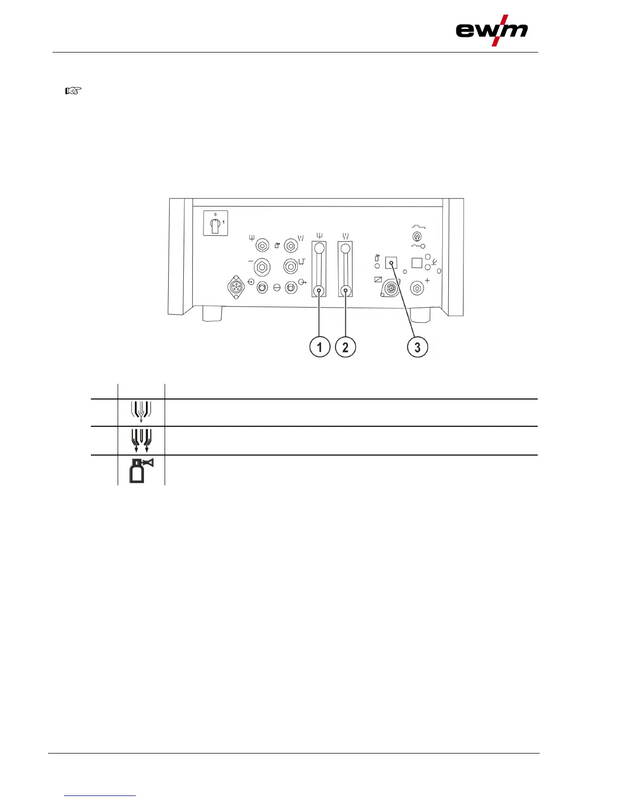
Figure 4-9
Plasma gas flow regulator
Control and display of gas flow volume
Shielding gas flow regulator
Control and display of gas flow volume
Gas test push-button > see 4.1.7.3 chapter
• Press and hold the shielding or plasma gas test pushbutton.
• Release the pushbutton (test procedure complete).
• Press the torch trigger and set the shielding gas quantity with the flow gauge of the pressure regulator.
The flow quantity cannot be set higher on the gas flow regulator for fine adjustment of the gas flow than
specified on the shielding gas cylinder pressure reducer.