Operation
Figure17
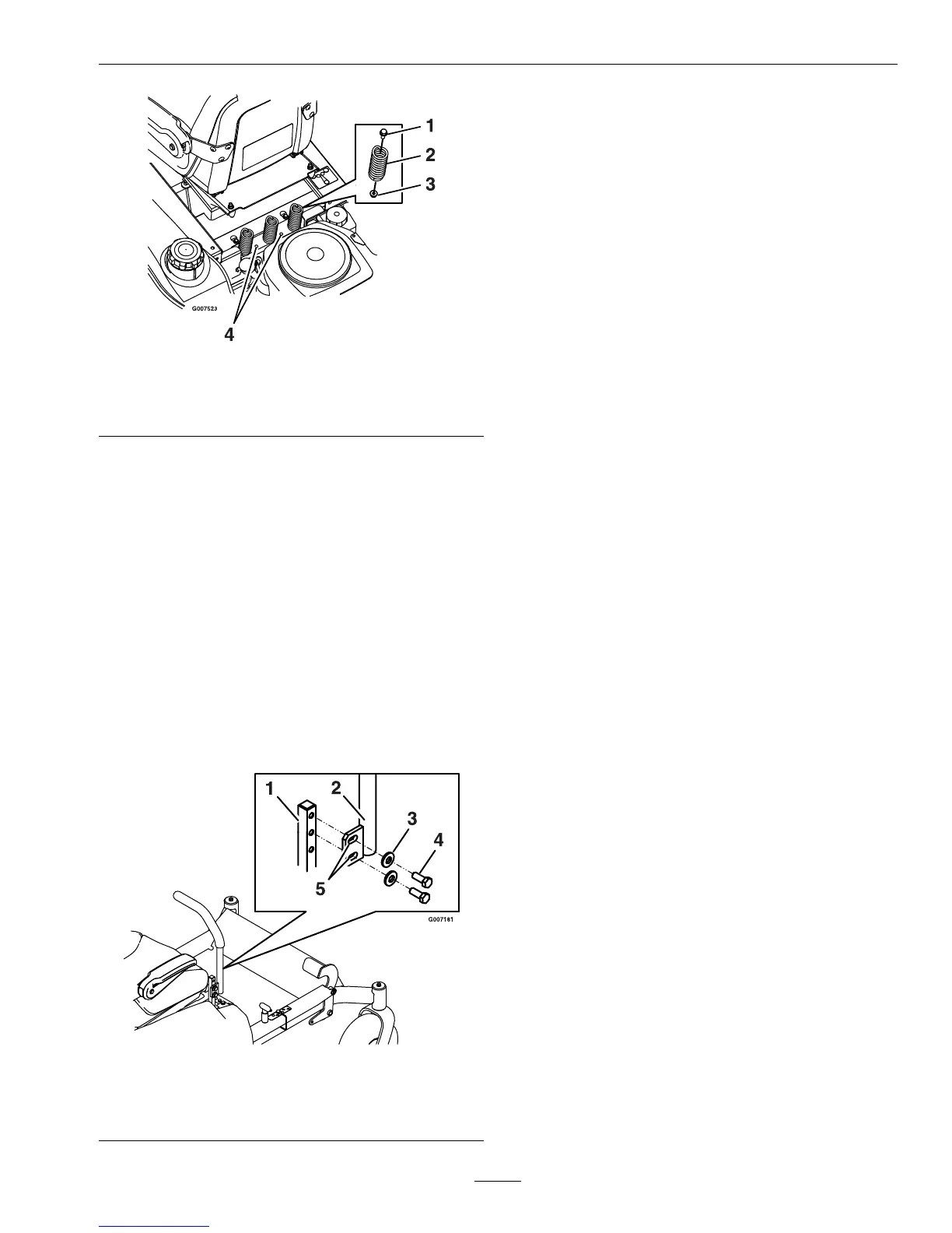
1.Bolt3.Nut
2.Spring
4.Additionalmounting
holes
Uptovespringscanbesecuredtotheseatboxwith
anutandbolt,seeFigure17.
RefertoyourPartsManualforspringandhardware
partnumbers.
AdjustingtheMotionControl
Levers
AdjustingtheHeight
Themotioncontrolleverscanbeadjustedhigheror
lowerformaximumoperatorcomfort.
1.Removethetwoboltsholdingthecontrolleverto
thecontrolarmshaft(Figure18).
Figure18
1.Controlarmshaft
4.Bolt
2.Controllever5.Slottedholes
3.Washer
2.Movethecontrollevertothenextsetofholes.
Securetheleverwiththetwobolts.
3.Repeattheadjustmentfortheoppositecontrol
lever.
AdjustingtheTilt
Themotioncontrolleverscanbetiltedforeoraftfor
maximumoperatorcomfort.
1.Loosentheupperboltholdingthecontrollever
tothecontrolarmshaft.
2.Loosenthelowerboltjustenoughtopivotthe
controlleverforeoraft(Figure18).Tightenboth
boltstosecurethecontrolinthenewposition.
3.Repeattheadjustmentfortheoppositecontrol
lever.
PushingtheMachineby
Hand
Important:Alwayspushthemachinebyhand.
Nevertowthemachinebecausedamagemay
occur.
ToPushtheMachine
1.Parkthemachineonalevelsurfaceanddisengage
thebladecontrolswitch.
2.Movethemotioncontrolleversoutwardto
neutralposition,engageparkingbrake,stopthe
engine,removethekey,andwaitforallmoving
partstostopbeforeleavingtheoperatingposition.
3.Locatethebypassreleaseknobsoneithersideof
theenginedeck(Figure19).
25