FX15 Controller Technical Bulletin
40
41 51 55 6242 52 56 6343 53 5754 6144 45 46 47 48
DO1 Com
DO4 no
DO5 no
DO4/5 Com
DO6/7/8 Com
DO2 Com
DO3 Com
DO1 no
DO8 no
DO7 no
DO6 no
FAIL no
FAIL Com
FAIL nc
DO2 no
DO3 no
Max
8(3)250V~
TB6
TB5TB4
TB3
FX16-026_11 2003
Group #6Group #5Group #4Group #3Group #2Group #1
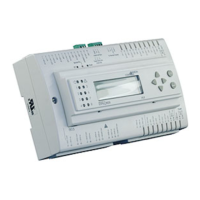
Figure 40: Relay Groups
Inside each group, the relays have just single isolation and thus must be
connected to the same voltage supply. Between the groups, there is a
double isolation and thus the groups can be connected to different
voltage supplies.
Figure 41 displays a typical application of the relay outputs as
connection example.
54
DO6 no
DO8 no
575655
DO7 no
DO 6/7/8 Com
~ 230Vac
Speed1
Speed2
Speed3
N
L
Fan
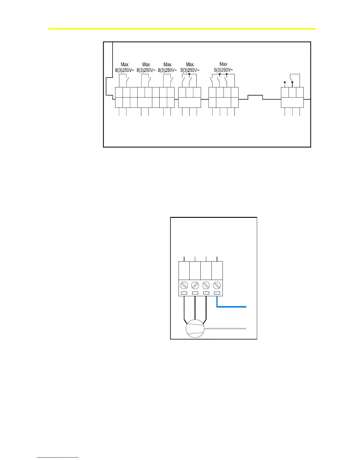
Figure 41: Connecting a Three-Speed Fan Motor
Note: Relays DO6-DO8 are not hardware interlocked and incidental
energization of more than one relay at the same time might lead to fan
motor damaging.