FX15 Controller Technical Bulletin
30
Analog Inputs
The six high-resolution analog inputs can be configured to accept a
wide range of voltage, current and resistive input signals.
See I/O Technical Details for the complete FX15 I/O table.
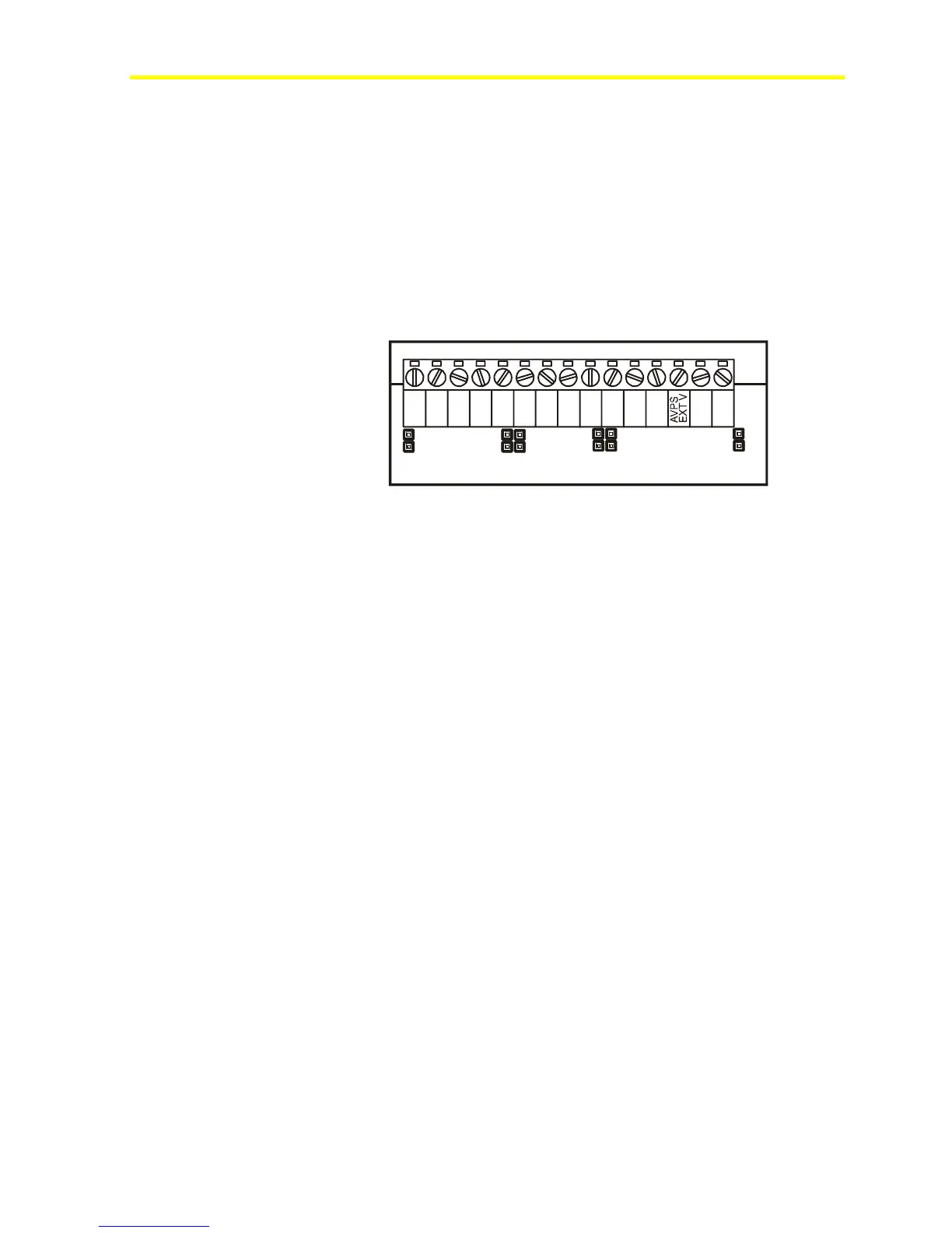
A dedicated jumper is placed on board for each analog input. This
jumper should be installed in its closed position if the connected sensor
provides a current signal (0-20/4-20 mA). This jumper should be
installed in its open position if the connected sensor provides a resistive,
ratiometric, or voltage (0-2/0-10 V) input signal.
a
AI1 AI2
AI3
I4
I5
I6
FX16-025_10 2003
AGND
AGND
AGND
AGND
AGND
AGND
AI1
AI2
AI3
AI4
AI5
AI6
EXT V
EXT V
Figure 31: Analog Input Jumpers
The active sensor (voltage or current) inputs are ranged using
programmable range parameters within the application software. These
parameters, HighRange and LowRange, define the equivalent values for
reading at High (10 V, 20 mA) and Low (0 V, 4 mA, 0 mA) signal
input. Voltage and current inputs from differential pressure transducers
can be linearized by a square root function (SQRT), which operates
over the complete range of the input.
The passive sensors (resistance) have a preprogrammed linearization
curves within the application software. For these sensors, the
measurement range is fixed. The user can set the reliability range via
software.
The read signal is converted by the FX15 according to the related
Analog Input object setup, available setup are:
• Linear 0-10 V
• SQRT 0-10 V
• Linear 0-10 V, 20% suppression (2-10 V)
• Linear 0-2 V
• SQRT 0-2 V
• Linear 0-2 V, 20% suppression (0.4-2 V)
• Linear 0-20 mA
• SQRT 0-20 mA
• Linear 0-20 mA, 20% suppression (0.4-2 mA)
• Resistance 2k ohm