FX15 Controller Technical Bulletin
5
Installation
This chapter takes you through the process of installing an FX15.
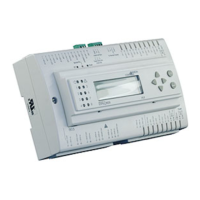
179 (7.05)
44 (1.73)
75 (2.95)
215 (8.46)
122 (4.8)
142 (5.59)
35 (1.38)
66 (2.6)
49 (1.93)
BB
Figure 2: Mounting Dimensions for FX15 (Shown with Integral User
Interface and Screw Connectors)
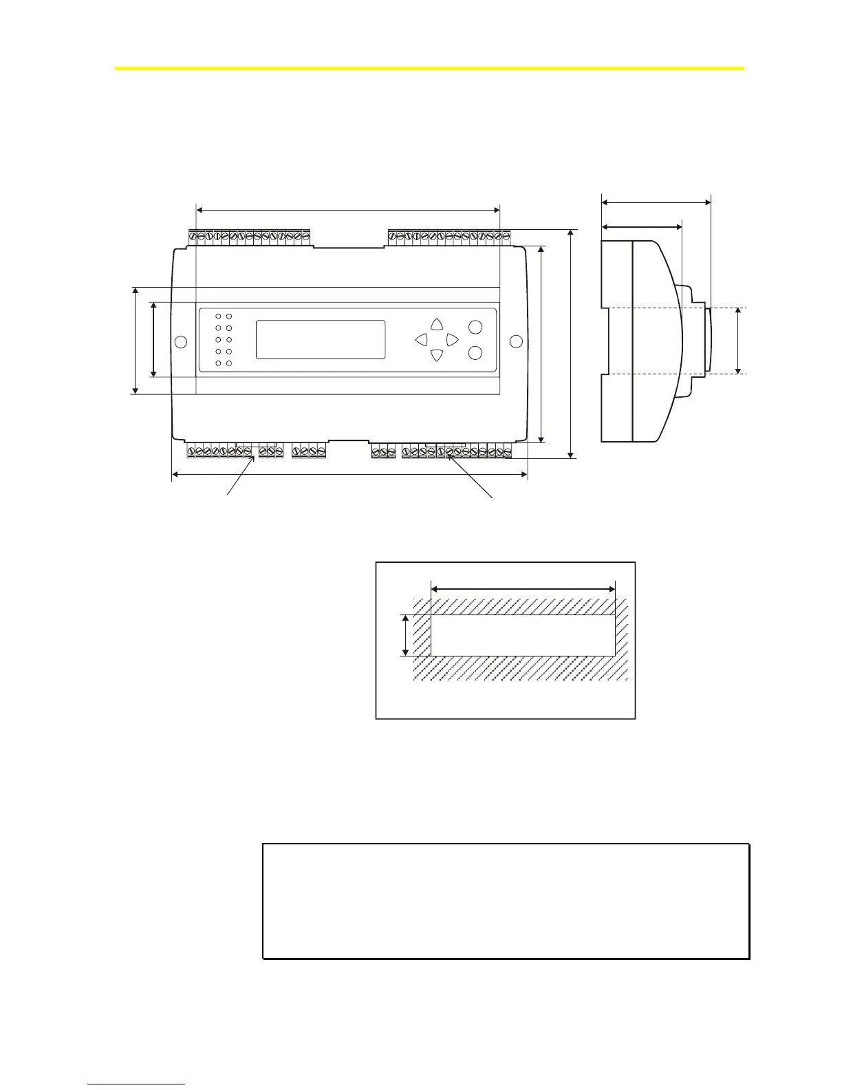
46.5 (1.83)
180.5 (7.11)
Panel cut-out
Figure 3: Panel Cut-Out Dimensions for User Interfaces
Two different types of terminal connectors are available: spring clamp
or screw connectors. The screw connectors are included, while the
spring clamp connectors must be ordered separately. For details, see
Ordering Codes.
IMPORTANT: For installation with Class 2 inputs and outputs only, no
special mounting precautions are generally necessary. For use with one or
more line voltage outputs (above 30 V), installation as part of a UL 508A
industrial control panel may be required by the local building or electrical
authority. These controllers are presently UL Recognized as Temperature
Indicating and Regulating Equipment in accordance with UL 873. UL Listing as
Open Energy Management Equipment per UL 916 is pending.