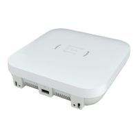
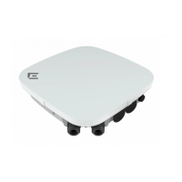
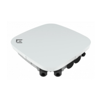
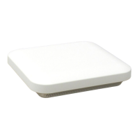
Figure 6: 1-axis tilt bracket
Procedure
1. Attach the at part of the KT-147407-02 bracket to the access point using two M6
screws.
2. Using the 1-axis tilt bracket as a template, mark and drill four holes on a wall or on a
at surface.
3. Attach the 1-axis tilt bracket to a wall or at surface using four M6 headsize screws.
4. Align the 1-axis tilt bracket part inside the at part of the KT-147407-02 bracket, and
attach the at bracket to the 1-axis tilt bracket using four M6 screws.
5. Tilt the access point to a desired angle and tighten the four M6 screws to a torque of
45 in-lbs.
The tilt bracket has +15 degrees to -15 degrees of tilt.
Install the Access Point
Install the Access Point on a Wall or Flat Surface Using
the KT-147407-02 Bracket Parts
ExtremeWireless™ AP560h Access Point 23
 Loading...
