MLC Plus 50/100/200 Series • Hardware Features and Installation 15
Installation Step 4: Cable All Devices
NOTE: Most examples on the following pages show the MLCPlus100. However,
connector wiring and port functions are identical for all models.
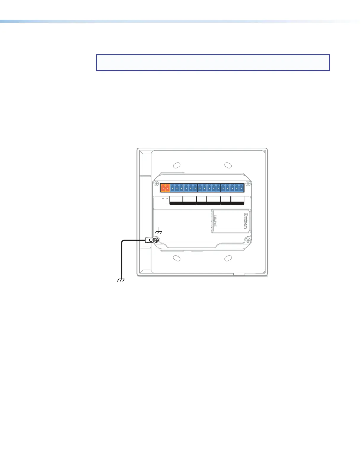
1. If the MLC Plus is not mounted to a grounded metal junction box or a grounded metal
equipment rack, Extron recommends connecting the unit to an earth ground to protect
the unit from electrostatic discharge.
To ground the unit:
a. Securely terminate a grounding cable with a ring terminal.
b. Remove the grounding screw in the lower left corner of the rear panel, insert the
grounding cable, replace and securely fasten the screw (hand-tighten only). Do not
over-tighten the screw. Maximum torque is 2 inch-pounds (0.2 Newton-meter).
LAN
/
PoE
POWER
12V
0.3A MAX
Tx Rx
G
Tx Rx
2CGCVGS
COM 1 COM 2 VOLIR
GIN
D IN RELAYS
Figure 13. Connecting a Grounding Wire to the MLC Plus
c. Connect the other end of the grounding cable to an earth ground.
2. Cable devices to the controller (see Rear and Side Panel Features and Cabling on
the next page). Use the wiring diagrams in this section as a guide.
3. Connect power cords and power on all the devices.
Rev. C,
01/24/18:
Added a
step to
ground the
unit.