MLC Plus 50/100/200 Series • Hardware Features and Installation 16
Rear and Side Panel Features and Cabling
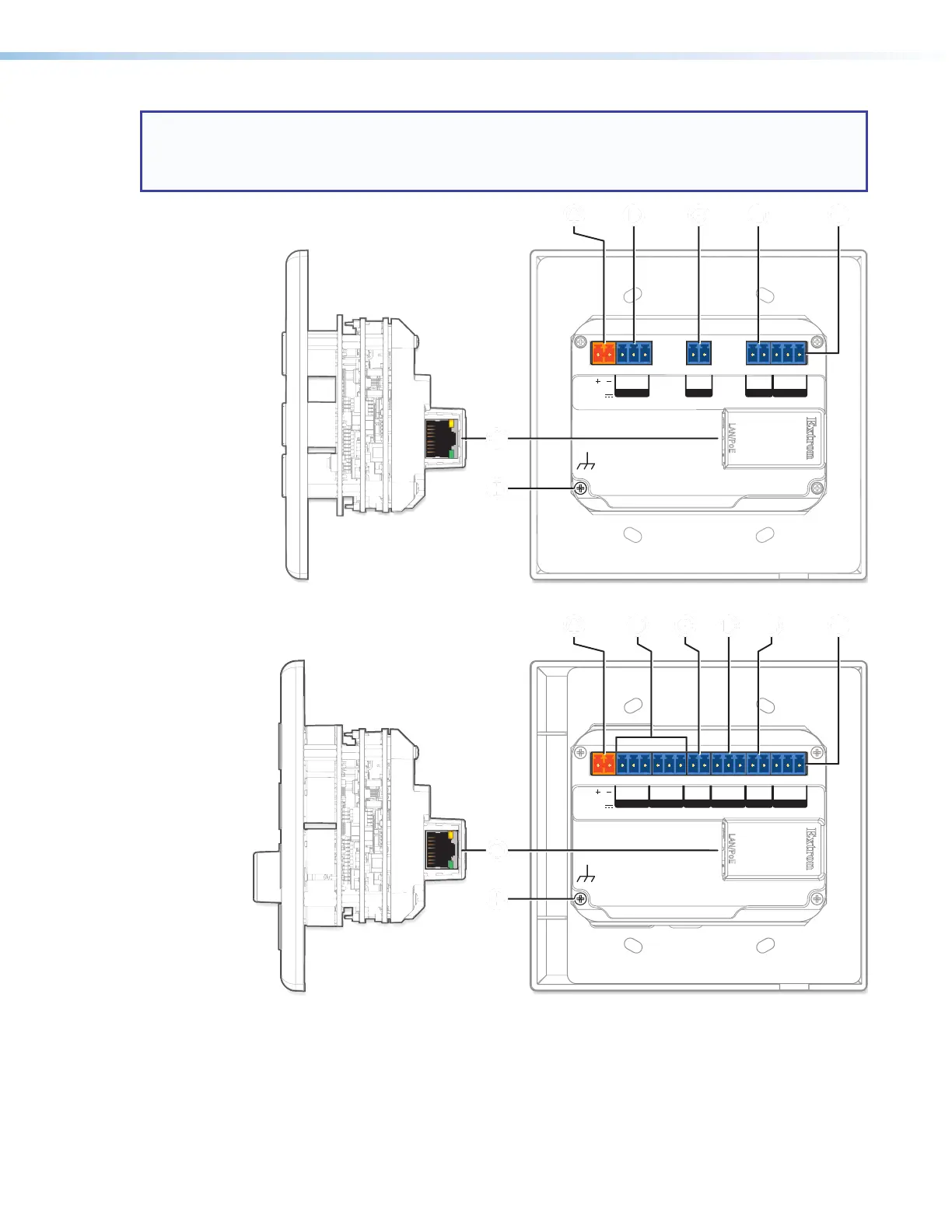
NOTE: For rear panel features and cabling, the MLCPlus100, MLCPlus100AAP, MLCPlus200, and
MLCPlus200AAP are identical, so in this section the MLCPlus100 represents all of those models.
The rear panel of the MLC Plus 50 has one COM port instead of two, and does not have a volume
control port, but it is otherwise the same as the other models.
LAN
/
PoE
LAN
/
PoE
POWER
12V
0.3A MAX
Tx Rx
G 12CGS
COM 1 IR
GIN
D IN RELAYS
POWER
12V
0.3A MAX
Tx Rx
G
Tx Rx
2CGCVGS
COM 1 COM 2 VOLIR
GIN
D IN RELAYS
MLC Plus 50 Rear Panel
AAAA B
BBB C
CCC EEEE FFFF
AAAA B
BBB C
CCC DDDD EEEE FFFF
MLC Plus 100
Right Side
MLC Plus 50
Right Side
GGGG
GGGG
HHHH
HHHH
GGGG
Figure 14. MLCPlus50/100/200Series Side (Left) and Rear Panel (Right) Features
A
Power input connector, page17
E
Digital input port, page22
B
COM (RS‑232) ports, page19
F
Relay ports, page23
c
IR output port, page20
G
LAN (Ethernet) and PoE port and LEDs, page18
D
Volume control port, page21
H
Grounding screw, see the grounding instructions on
page15