MLC Plus 50/100/200 Series • Hardware Features and Installation 22
E
Digital input port — Connect a switch, sensor, LED, relay contact, or similar item to
this port, which can be configured with or without +5VDC pull-up. The port can trigger
events or functions (such as
triggering relays, issuing commands,
or sending an e-mail) that have been
configured using Global Configurator.
To allow the controller to monitor
external devices, connect a switch,
motion sensor, moisture sensor, tally
feedback output, button pad, or a
similar item to a digital input port and
configure the port. The port is set to
measure two states: high and low.
The port accepts 0 to 24VDC input.
Threshold voltages are not
adjustable. The thresholds are as
follows:
• < 2.0VDC — port on, logic low
• > 2.8VDC — port off, logic high
There is also an internal, +5 VDC, selectable, pull-up resistor for this circuit, which you
can use if the connected device does not provide its own power. The port is capable of
accepting 250mA, maximum.
• Digital input with pull-up disabled
• Digital input is triggered by an external switch or voltage between the digital
input pin and ground.
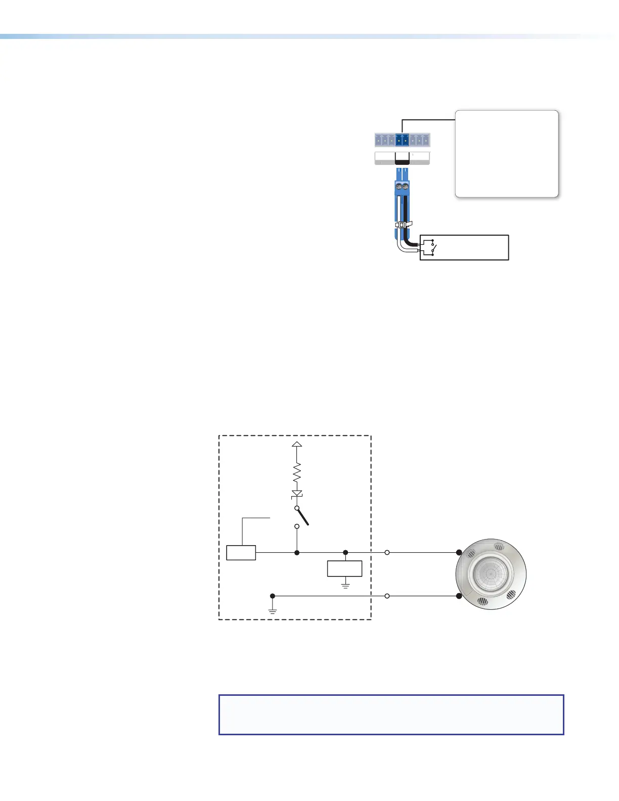
• Example application, digital input without pull-up: occupancy sensor
connection
Control
Signal
Ground
+5.0 V
1k ohms
SW 2
Digital
Input
GND
Voltage
Protection
CTL
Occupancy
Sensor
Figure 21. Digital Input Application:
Occupancy Sensor, Without Pull‑up
Room occupied: digital input is +2.8 to 24 VDC, logic high.
Room unoccupied: digital input is 0 VDC, logic low
NOTE: Occupancy sensors typically supply +24VDC (logic high) when
occupancy is detected. After a set time with no occupancy, the sensor
supplies 0VDC (logic low).
V
L
GIN
D IN
ELAY
Digital Input
Congure the port with or without
+5 VDC pull-up.
Use this port to:
• Monitor or trigger events and
functions (toggle relays, issue
commands, send e-mail), once
congured.
• Power an LED or other device
that accepts a TTL signal.
nel
Switch, Sensor, LED,
Relay, or Similar Item)
Figure 20. Digital Input Port Wiring
Rev. C, 01/26/18:
Added details and circuit examples
for digital input.