MLC Plus 50/100/200 Series • Hardware Features and Installation 25
Installation Step 7: Test and Troubleshoot
1. Test the system.
• Press buttons and ensure the buttons light as desired and that the appropriate
control commands or functions are triggered.
• Ensure that the audio output responds correctly to the Volume knob or button.
Also ensure that the volume LEDs light correctly as you increase or decrease the
audio gain.
• If the controller is connected to a network, ensure that the yellow Activity LED and
green Link LED on the LAN/PoE port light.
2. Make adjustments to wiring or configuration as needed. Remember that the rear and
side panel ports are not accessible after the controller is mounted.
Installation Step 8: Complete the Physical Installation
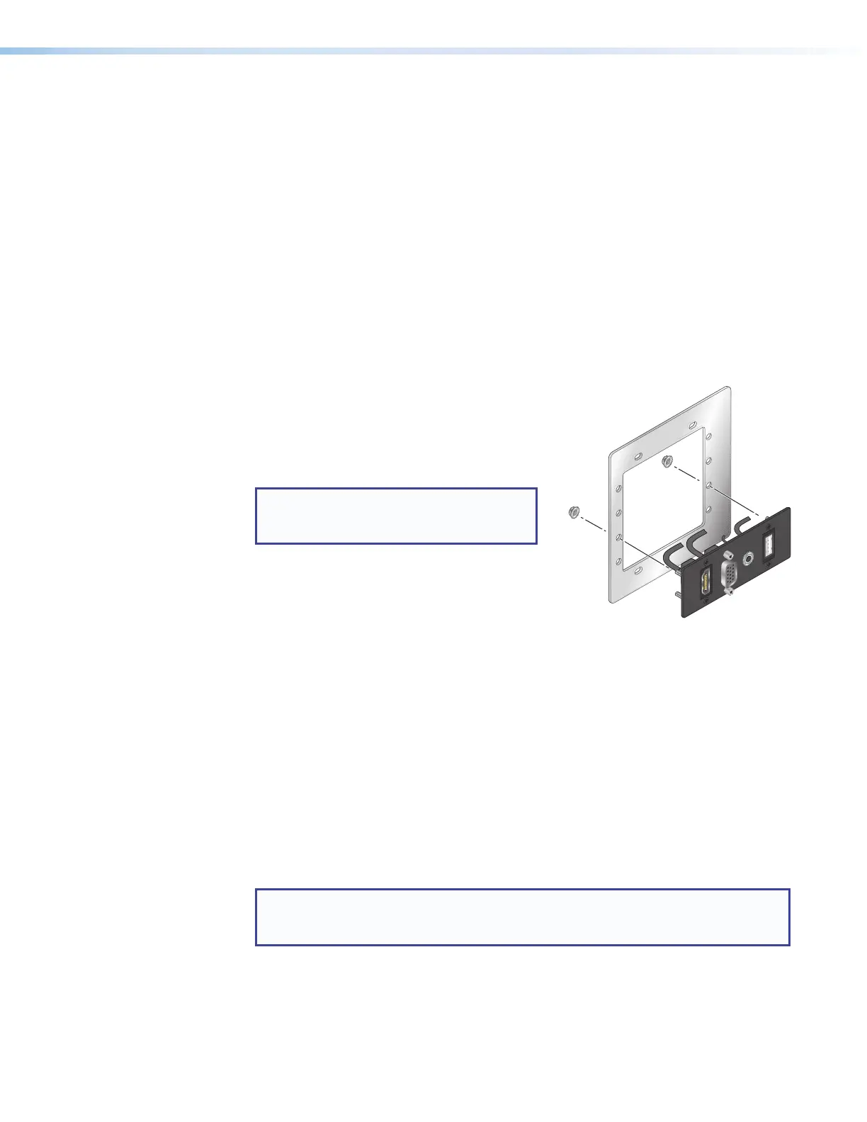
1. For AAP models, attach any optional AAP devices or blank AAP plates to
the metal AAP bracket as shown in the figure at right.
Insert the built-in screws of the AAP device
through the holes in the metal AAP bracket
and hand tighten to fasten them to the bracket
with the provided nuts.
NOTE: You must purchase AAP devices
and plates separately. They are not
provided with the MLC.
• Place the AAP devices as close together
as possible. Do not leave gaps between
devices.
• Place the AAP opening of the MLCPlus
faceplate over the cluster of AAPs to check
for correct fit. Make sure that the edges
of the AAPs all fit within the faceplate AAP
opening so that no edges or corners catch or
prevent the faceplate from laying flat against
the AAP mounting bracket. If needed, loosen the nuts, adjust the position of one or
more AAPs, and retighten the nuts.
2. For all models, follow the instructions in Mounting.
Mounting
Prior to mounting:
1. If it has not already been done, feed all device cables through the wall or furniture and, if
applicable, through the plastic spacer.
NOTE: If the unit is not installed in a mud ring, you must install the plastic spacer.
The spacer positions the unit to allow the magnetic faceplate to attach properly
and securely.
2. Ensure that cables are connected to the MLCPlus rear panel and to any AAP devices
or plates. For best results, Extron recommends grounding the MLC if the junction box or
mud rings are not already grounded (see grounding instructions on page15).
3. Disconnect power at the source from all devices in the system.
VGA
HDMI
VGA
AUDIO
USB
Figure 25. Attaching AAP
Devices or Blank
AAP Plates to the
AAP Bracket
Rev. C,
01/23/18:
mentioned
grounding
the unit.