MLC Plus 50/100/200 Series • Hardware Features and Installation 20
C
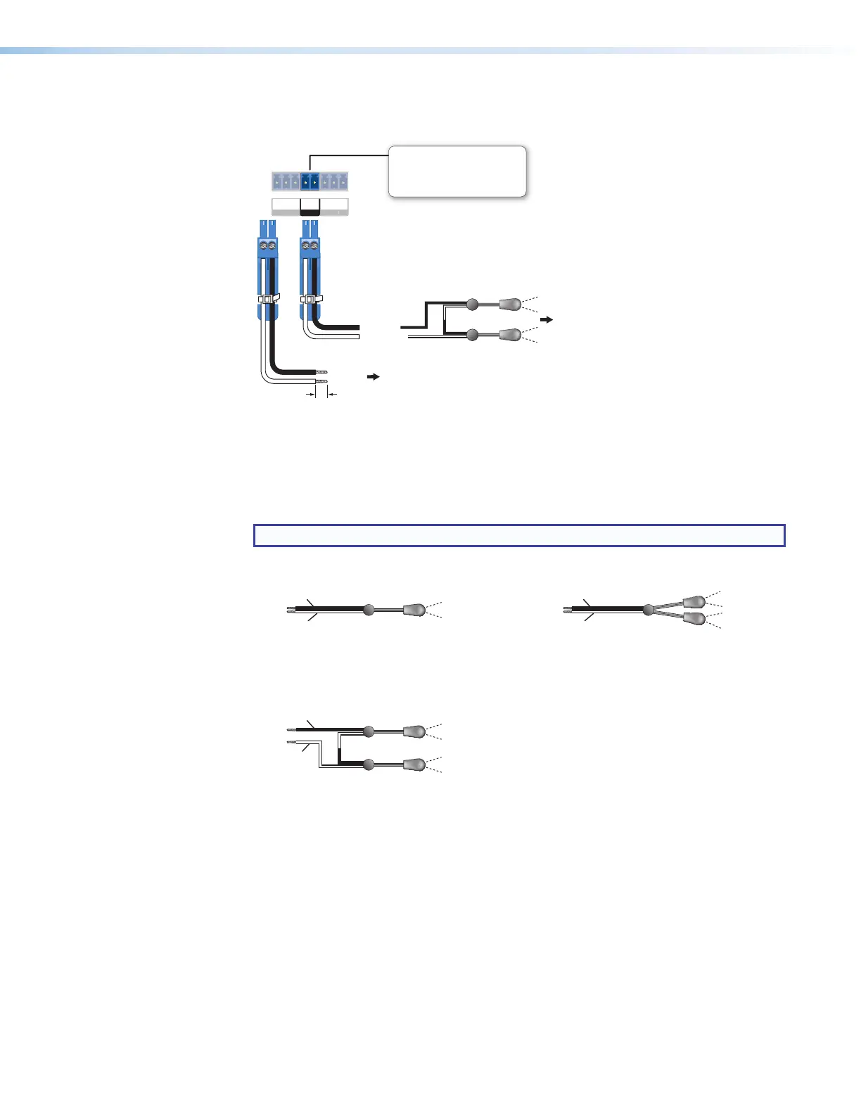
IR output port — An MLCPlus50/100/200 Series controller can use infrared signals
to control up to two devices via this port.
T
x
GS
M 2 V
LIR
Rear
Panel
S
G
(-)
(+)
(-)
(+)
(+)
(-)
To the
a Projector,
Display, or
Source Device
Two Single IR Emitters
Ground
IR Output
Ground
IR Output
Unidirectional IR
or
To Projector, Panel Display, or the Wired
IR Remote of a Source Device
IR Output Port
Output options:
• IR (30 kHz to 300 kHz,
with or without carrier signals)
Figure 18. Wiring the IR Port
Connect the port directly to the wired IR port of another device. Or insert the wires from
up to two IR Emitters into this IR port and place the heads of the emitters over or next
to the IR signal pickup windows of the devices. For wiring, see the following diagrams
or the IREmitter Installation Guide (available on www.extron.com).
NOTE: Each emitter must be within 100 feet (30 m) of the controller for best results.
Installing One Single Emitter Installing One Dual Emitter
Ground (−)
IR Signal (+)
Ground (−)
IR Signal (+)
Installing Two Single Emitters
When installing only single emitters, tie them in series as shown below.
(+)
(−)
(−)
(+)
IR Signal (+)
Ground (−)
Two Single IR Emitters