MLC Plus 50/100/200 Series • Hardware Features and Installation 19
Control
B
COM ports, RS-232 only — Use COM ports for serial control of a display or other
device and to receive status messages from the connected devices. These ports can
send commands from a driver file. These ports support only RS-232 communication.
MLCPlus Series Serial protocol:
• 300 to 115200 baud (9600 baud = default)
• 8 (default) or 7 data bits
• 1 (default) or 2 stop bits
• No parity (default), even, or odd parity
• Flow control support (default = none):
software-only (XON, XOFF)
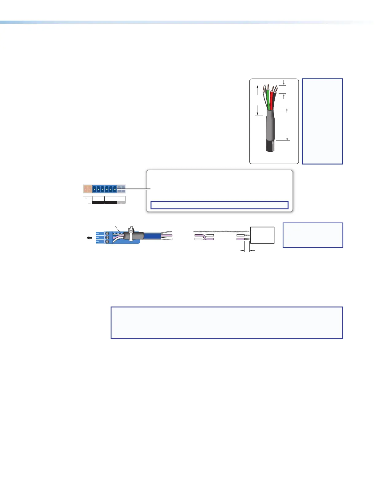
Use the following diagram as a wiring guide to
cable the controller to other devices.
Tx Rx
G
Tx Rx
G
OWER
.4
COM 1 COM 2
NOTE: If you use cable
that has a drain wire,
tie the drain wire to
ground at both ends.
Strip wires
Transmit
Receive
Transmit (Tx)
Receive (Rx)
Ground
RS-232-
Controllable
Device
Rx
G
Tx
3-pole COM
(RS-232)
Select protocol via software. COM port default protocol:
• 9600 baud
• 8 data bits • 1 stop bit
• no parity • no ow control
NOTE: These COM ports support software ow control only.
Serial (COM) Ports
Rear Panel
Heat Shrink
Over Shield Wires
3-pole
Figure 17. Wiring COM Ports for Serial Control
For bidirectional serial communication, the transmit, ground, and receive pins must be
wired at both the controller and the other device. Each projector or other device may
require different wiring. For details, see the manual for that equipment or read the Extron
device driver communication sheet, which is included with the drivers.
NOTE: Maximum distances between the MLCPlus and the device being
controlled may vary up to 200 feet (61 m). Factors such as cable gauge, baud
rates, environment, and output levels (from the MLCPlus and the device being
controlled) all affect transmission distance.
3/16"
(5 mm)
Max.
7/8"
(22 mm)
Heat Shrink
on Outer
Jacket to
Inner
Conductor
Transition
Extron
STP 20-2P Cable
TIP:
STP 20-2P
cable, shown
at left, is
recommended
for these
connections.
For best
results,
insulate the
common or
drain wires
using heat
shrink.
Rev. C,
01/23/18:
replaced
CTL/CTLP
cable with
STP 20‑2P
cable.
Rev. C,
01/23/18:
Deleted
mark and
space
parity.